In 2006-2008 I performed research, scenario design, and defined the user experience strategy for the IBM Rational Global Development and Delivery offering
What is Global Development and Delivery
Global development profiles organizations with a distributed team dispersed across towns, across the borders, or overseas. Teams may be Onsite, Nearshore, Offshore, or Outsourced. Generally, hybrid structures are used. Onsite and Nearshore and often internal staff. Nearshore and Offshore are often directly owned subsidiaries or joint partnerships. Outsourced covers contracts with the service provider that supplies supplemental resources or assumes responsibility for all or part of the software development lifecycle.
While the user of global resources often lowers the cost of staff, additional pains arise. Mismatched and Misunderstood Processes. Communication Issues. Cultural Issues. Decrease Productivity. Increased Rework. Mistakes in Work-Transfer. Higher Coordination Costs. Political Issues. Security IP Protection. Lack of Project Visibility, Agility, and Control. Unable to Measure Success.
Support for GDD best practices can change the equation. Process, Workflow, and Development challenges can be addressed by improving team efficiency across cultures and geographies by automating the full lifecycle processes and development tools. Communication and Collaboration challenges can be improved by accelerating project success through collaborative team-based development and a workplace environment. Project Management & Portfolio Management challenges can be improved by providing global visibility through accurate project metrics and reporting.
Researching Global Development and Delivery
I researched global organizations in the US, Europe, and India that depend on global development and delivery or deliver outsourcing services to uncover the root causes of the challenges reported above. The following root causes were identified.
Communications issues – time lag, cultural
Requirements not well-defined upfront
The requirements management process does not provide a feedback loop or method for communicating changing / evolving requirements
Requirements well defined, but not well communicated
Organizational issues – lack of motivation
Process (handoff, delivery, change management) not well understood – time spent trying to figure out who does what
Additional project management overhead
Mismatched and unsynchronized configuration management processes and systems – resulting in classic configuration management problems – work to know what files to work on, what is the latest build, why did the build break, etc.
The end product, not the right product (requirements mismatch)
The end product has a high defect density
The offshore testing process not aligned with onsite needs
Requirements changes not reflected in product
Enhancement requests not reflected in product
Poorly defined deliverables
Wrong versions delivered for integration and deployment
Conclusions on User Research
The metrics from the research show that
Productivity may decrease by up to 50%
Typically localized project rework is 20%-30%
Distributed development: 50%-100% rework in initial projects
The research also shows two emerging client topologies
Centralized
Single centralized server hub
Local LAN access – thick clients
Remote WAN access – thin web clients
Distributed/Replicated
Multisite backbone with server hubs
Local LAN access – thick clients
Remote WAN access – thin web clients
Integration with open source SCM tools like Subversion
The research identified new trends impacting our GDD design strategy
The enterprise development model is challenging
Consolidate infrastructure to centralized hubs
Connect global teams with remote access
Connect global teams into supply chains
Be aware of competitive pressure from open source
Needs on GDD called out by our Board of Advisors
Need to launch new projects quickly
Need to provision new global sites quickly
Collaboration between distributed teams are key to success
Formulating a GDD User Experience Strategy
Based on my analysis we formulated a GDD UX strategy
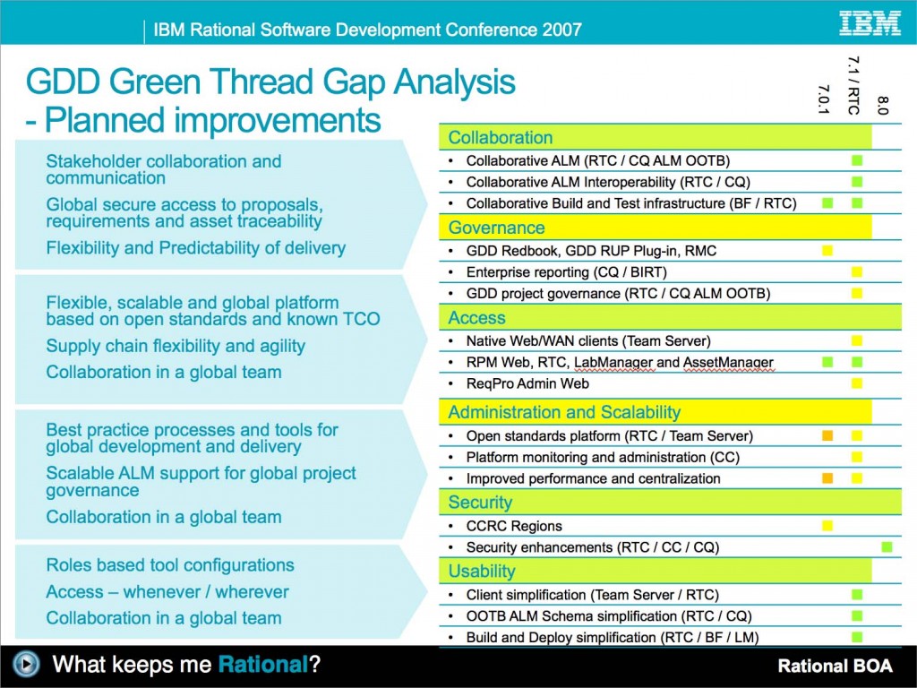
7 Views identifying the key aspects of global delivery
Collaboration
Governance
Access
Administration and Scaleability
Security
Usability
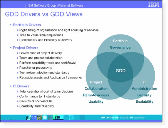
GDD Drivers identifying the stakeholders and their incentives
Portfolio drivers
Project drivers
IT drivers
We also formulated a hill for GDD that ‘Global organizations can grow development capacity and achieve cost savings by providing a centralized the development infrastructure with remote access to global teams’
This UX strategy was driving our
Design scenarios for GDD
Product strategies approved by the GDD Offering Team
Collaborative Lifecycle Management Information Model
The leading ALM solution from IBM is the Collaborative Lifecycle Management (CLM), which consists of Rational Requirements Composer (aka Rational DOORS NG), Rational Team Concert, Rational Quality Manager, and Rational Design Manager. The Jazz platform is strategic for implementing the Rational solution for CLM. The Jazz platform is all about collaboration; it allows individual products to integrate better and more easily, and allows the users of those products who take on distinct roles to work more effectively together than has historically been possible. The Jazz platform supports a more collaborative approach to ALM tools and their users. The approach is open. It leverages the standards used by the Internet. Just as the internet works with data spread around the world, the approach is to allow development team data to be spread around an organization, and yet to have development artifacts as easily accessible as surfing the world-wide-web. Through the support for OSLC, integrations can be provided for Jazz-based products. Additionally, third-party vendors and customers can consume or provide their own OSLC interfaces to support heterogeneous environments made up of Rational, third party, and/or customer solutions. The combination of Jazz and OSLC provides the ability to have unprecedented collaboration, transparency, automation, and traceability.
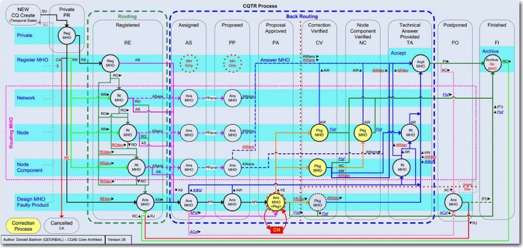
What’s wrong with Change Management State Schemas?
The artifact information model used by the Collaborative Lifecycle Management solution, adopted and extended in the IoT Collaborative Engineering solution, is radically different compared to classic change management and lifecycle tools like Rational Clear Quest. In CQ the complete lifecycle was managed in the complex schema. In CALM the state is distributed over a network of linked and related artifacts. User research on the use of schema-based change management systems identified user pain points
Complex information schemas modeling artifact types and lifecycles all in ONE schema.
Weak integrations across lifecycle tools with demands on data synchronization across repositories. Most schemas reference other schemas on the same installation.
Limited plan information allows teams to plan changes and work using agile methods
Support for centralized deployment or multisite synchronization
Support for rich client installation at every user desktop
Research at our enterprise clients reports on similar pain points in establishing a state schema, resulting in years in negotiating a corporate-wide schema in ClearQuest that managed the lifecycle of Change Requests as a single state model.
What’s new with Collaborative Lifecycle Management?
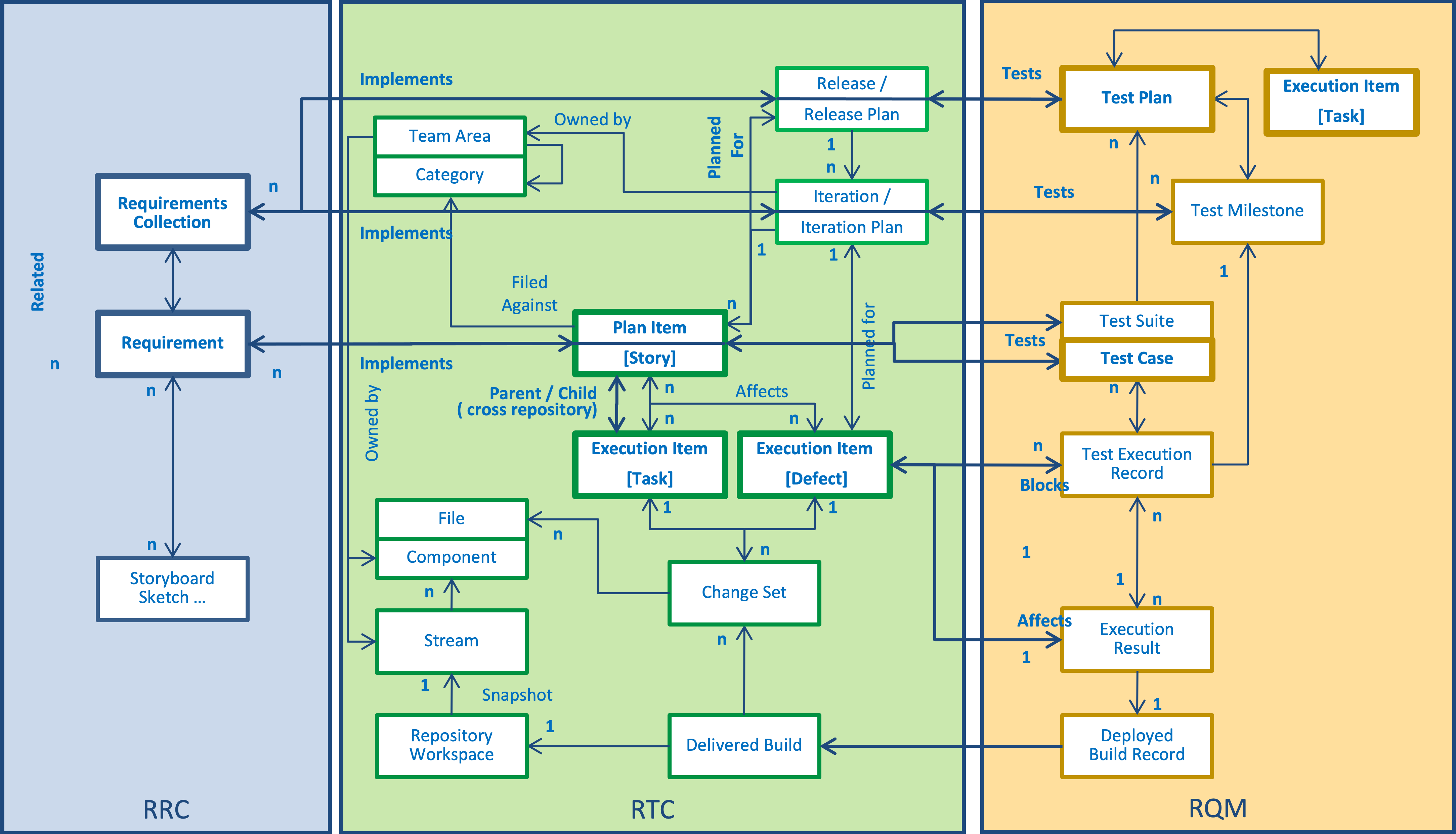
The artifact information model used by the Collaborative Lifecycle Management solution, adopted and extended in the IoT Collaborative Engineering solution, is radically different compared to classic change management and lifecycle tools like Rational Clear Quest. In CLM the state is distributed over a network of linked and related artifacts.
An application or system lifecycle is composed of multiple domains and disciplines; Requirements, Designs, Tests, Change Requests, and Plans
Each discipline defines a set of core artifact types. For example, managing tests needs the specification of Test Scripts, Test Cases, Test Suites, Test Plans, Test Results.
Each artifact has a state. A Requirements may be New, Reviewed, Approved, Implemented, Verified, and Delivered. Or even Duplicate or Withdrawn. The state forms a state model.
Artifacts have relations, or links, to other artifacts of the same or other domains. A Requirements is validated by a Test Case. A Defect is planned for an Iteration.
Artifacts have relationships. A Software Requirements satisfies a Subsystem Requirements, that in its turn satisfies a System Requirements, that in its turn satisfies a Stakeholder Requirement.
Artifacts have attributes that classify the type. A System Requirement, Subsystem Requirement, and Software Requirement all have shared and unique attributes. Some are mandatory, others are optional.
Links have types that carry semantic meaning. A link between two works items may, for example, be a Parent, Child, or Blocks.
The semantic interpretation of the link provides insights into the state of the systems. Identifying all Requirements in the current Iteration that has Blocking defects is a good insight into the readiness to release and any unstable/unavailable content of the release.
The artifact and state models are defined by the client organization and are tailored to implement the development process adopted.
The artifact link models are defined by the client organizations
Considering links to be URLs allows artifacts to be distributed over multiple services, locally or globally, and provides flexible centralized or distributed deployment options.
Let’s consider an example by walking the structure in the diagram
A Requirement is a part of a larger Requirements Module or Collection specifying a system or an application
A Requirement is implemented as a Story
The Story may be decomposed into Tasks and there may be Defects in the emerging implementation
The Story is planned for an Iteration in a Release
A Requirement and Story is tested by a Test Case
A Test Case will generate a Test Result in a Test Iteration / Milestone
A failing Test Case will result in a Defect on a Story
All tests are a part of a Test Plan testing a Release
Implementing a Story will create a Change Set of changes in a versioned File
Changes to a File is organized by Streams making sure that only related changes go into a Build
A Build is made up of Change Sets on versioned Files in a Stream
A Workspace is a collection of Streams that are integrated into a Build
Tests Cases generate Test Results on a deployed Build
Formulating an ALM User Experience Strategy
Based on our research we formulated the ‘ALM Principles’ that was validated by our sponsors
Development is not an island unto itself; it provides a service to the business
There are cycles within cycles many of which are ripe for automation
A Solution is created by a social network of people producing artifacts
Solutions never die, they are refined and maintained for years
Assets are Investments
Reporting on Collaborative Lifecycle Management
In 2009 I co-led the publishing of the CALM Redbook together with Carolyn Pampino and a group of Rational SMEs. The Redbook provides a blueprint for Collaborative Application Lifecycle Management by using an end-to-end reference scenario for deploying the new Rational products and ‘Agility at Scale’ into an existing enterprise environment. The scenarios produced for the Redbook cover Change Management, Requirements Management, Enterprise Integration Builds, and Test Management. It also discusses metrics for team success in Application Lifecycle Management.
“ALM is the thread that ties the development lifecycle together” – Forrester analyst Carey Schwaber”
Systems Lifecycle Management and Systems Delivery Scenarios
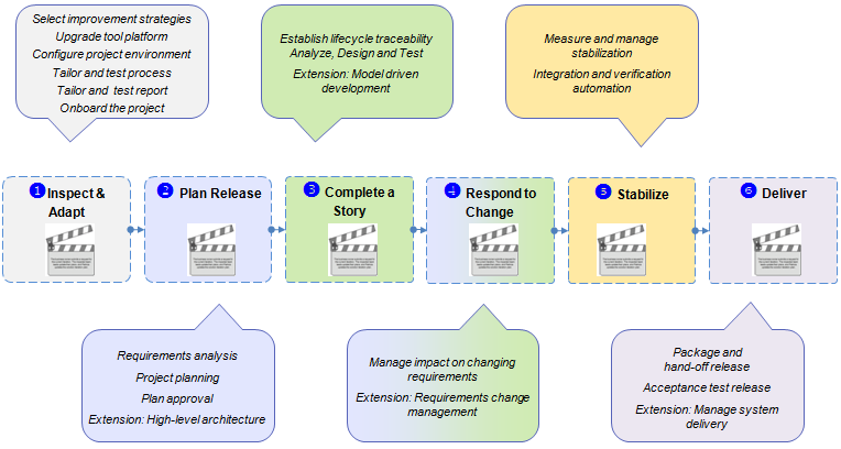
From this generalized CLM@scale lifecycle we focus the System Delivery scenario on a story in six acts. These acts focus the scenario on exploring key workflows and lifecycle capability requirements of a System Lifecycle Management solution and are designed to answer a primary lifecycle question that is critical to the success of the project. The six acts cover aspects of configuring the project, planning the project, delivering a part of the system, managing changing requirements, stabilizing the system release, and hand-off of the release.
These acts are common to the CLM scenarios. The figure indicates where specific extensions have been identified to explore system delivery scenes.
Act 1 – Inspect and Adapt
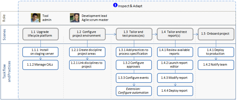
The project admin(s) and the project lead(s) are set up and configuring lifecycle management for the project. This act covers upgrading the system delivery platform to the latest release of the products. It also covers the deployment of new tools and capabilities in the system delivery platform. The act also includes how the project environment is configured and related CLM repositories are linked. Finally, it explores how the team selects an improvement strategy and how the practices and process automation used by the project is configured and deployed to the system delivery platform.
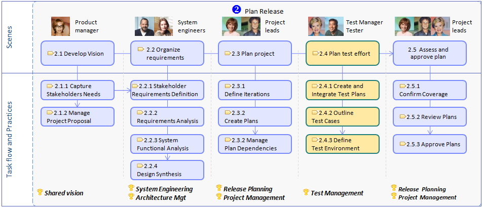
Act 2 – System Engineering / Plan Release. This act explores System engineering, Project release planning, and how these two practices interact in a System Delivery project. The act explores how system requirements engineering is supported by the tools on the System Delivery platform, and how Stakeholder Requirements, System Requirements, System Use-Cases, System Architecture relate to the project Iteration plans and Test Plans.
Act 3 – Complete a System Requirement. In this act one of the software delivery teams are planning, modeling, delivering, and integrating a sub-system use-case. This explores the use of model-driven development using the System Delivery platform. It also explores new development collaboration workflows using Modeling and CLM scenarios. The CLM@scale scenario reference this act as Complete a Story.
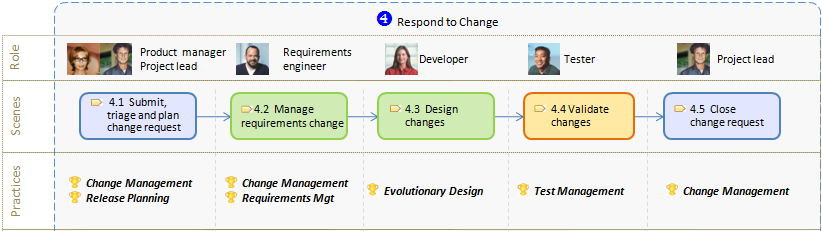
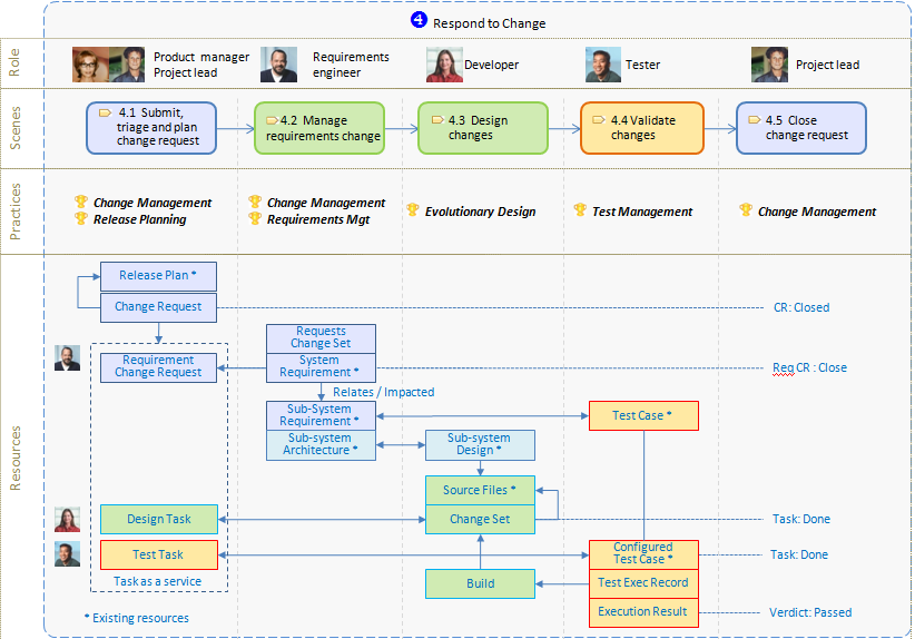
Act 4- Respond to Change. Requirements Change Management is a key capability for System Delivery teams. This act explores how new formal change requests are submitted, triaged, how the impact from change is analyzed, and how requirements are updated, reviewed, approved, and baselined.
Act 5 – Stabilize. Lifecycle Management with Jazz enables rich capabilities for monitoring project health through CLM queries. This act explores how reporting and Jazz Dashboards help the team ensure quality and prepare for the release.
Act 6 – Deliver. The team is handing off the system release.
Acts are broken into scenes to explore smaller, concrete goals. Browse the links above to learn more about the scenes in each act.
The Scenario Personas
The actors in the System Delivery scenario share common CLM scenarios personas. In some cases, the role name may be adjusted to suit the vocabulary and needs of the scenario. In summary, for this scenario, we use the following teams and roles
Project Management team
Ursula – Product Manager. Owner of the product. Prioritizes stakeholder needs.
Patricia – Project and Resource Manager. Responsible for project schedule & deliverables.
Scott – Development Manager. Managing the project development teams.
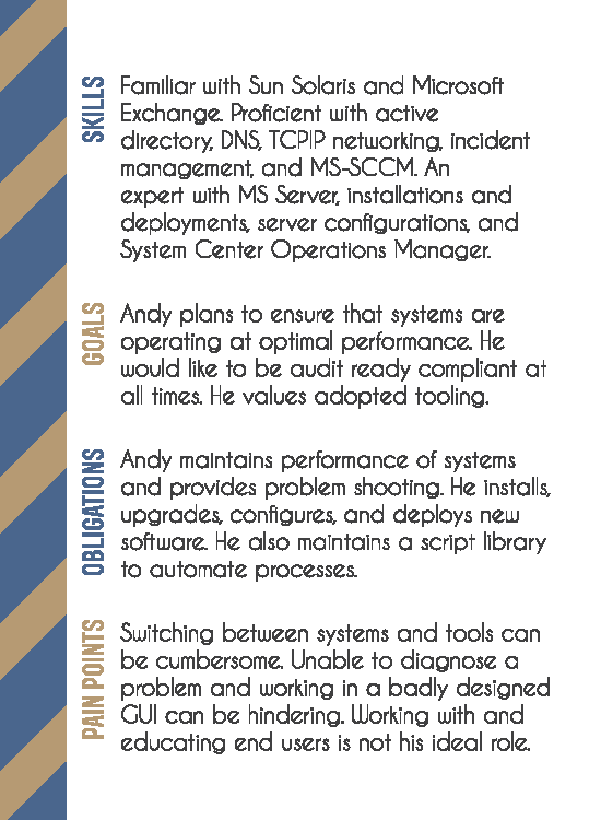
Andy – Project and tool administrator. Manages the project repositories and servers and clients used by the project.
System Engineering team
Bob – Requirements engineer. Responsible for system requirements.
Sally – System architect. Defines and validates the system architecture. Manages subsystem dependencies.
Software Engineering / Software subsystem team
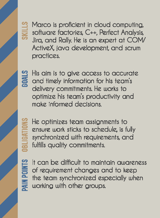
Marco – Software team lead and developer. Manages the agile plans for the software subsystem.
Al – Software subsystem architect. Responsible for the software architecture.
Deb – Developer. Practices model-driven development. Performs unit testing of her changes.
Tanuj – Tester. Validates the quality of the software subsystem.
Integration and Validation
Tammy – Test manager. Responsible for the overall quality of the system delivery. Leads the independent test team that performs integration validation, and system acceptance tests.
Rebecca – System integration engineer and Release engineer. Manages software integration builds.
Terry – Test architect. Responsible for test architectures and test configurations.
Systems Delivery with CLM – Act 1 – Inspect and Adapt
Synopsis
The System Delivery scenario story starts with the project team preparing the System Delivery platform for the new project. Andy, one of the project admin(s), deploys or updates the system delivery platform tools. Scott, the development lead, configures the discipline processes and reports for the project. Some of the steps in the scenes below are shared across the CALM scenarios. Other steps are scenario extensions for the System Delivery platform.
In this act, we are deepening our understanding about
Install and upgrade path for the capabilities in the System Delivery platform
How to configure a multi-repository and multi-discipline project
Scene Details
Install system delivery platform* – Andy upgrades existing servers and installs new servers. He configures and tests the server connections using OSLC.
Configure System Delivery Platform* – Scott configures new project areas and establishes links across the related project areas.
Tailor and test process(es) – Scott adds new discipline practices to the project process specifications. He tests and deploys the changes.
Tailor and test report(s) – Scott adds new reports from selected practices. He adopts the reports to the project. He updates the project dashboards.
Onboard project – Andy and Scott moves the project infrastructure to production and inform the project teams on how to use changes to process, reports, events, and dashboards
* Scenario extensions for system delivery
Systems Delivery with CLM – Act 2 – Plan release
Synopsis
In this act, we explore how the project is started. Our focus is on System Engineering and Project Planning.
The first scene explores how Ursula, the product manager, is establishing the concept for the project through managing the stakeholder needs and managing the proposal and approval of the system delivery project. We then switch to the next scene where the System Engineering team captures the system requirements, system use-cases, and how traceability is established between the system requirements. In the following two scenes, we explore how the project leadership team is transforming the prioritized system requirements into a project plan, development plans, and test plans. In the final scene, the project leaders are reviewing, approve, and baselining the project plans.
In this act, we are deepening our understanding about
How OSLC linking between Requirements, Architecture and Plan Items support System Engineering practices
How to plan a project or a program using multiple related project areas and iteration plans
Scene Details
Develop Vision and Concept – Ursula managed stakeholder requirements documents and change requests, and prepares a project proposal for approval.
Organize requirements – The System Engineering team analyzes the requirements.
Plan project – The project team plans the project.
Plan test effort – The test team plans the integration, verification, and validation test activities.
Assess and approve the plan – The project leadership team approves the project plans.
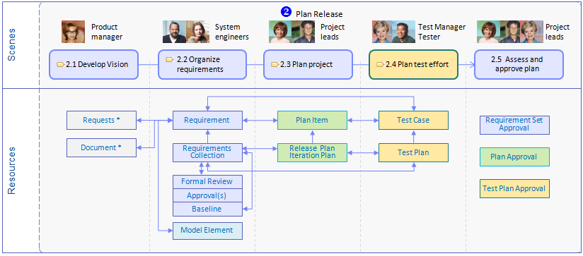
Lifecycle Management Resources
This act in the scenario focuses on two areas in the lifecycle management resource structure; the system requirements, and the plans of the project.
Systems Delivery with CLM – Act 3 – Complete a System Requirement
Synopsis
In this act, we use the System Development practices to explore how the team uses the System Delivery platform to realize system requirements as part of one increment/iteration.
The software sub-system team (in the system delivery project) is using an agile approach to iterative (incremental/spiral) development. Each project iteration is planned for about 4-6 weeks. The objective of each iteration is to realize and validate a set of system requirements and use-cases, resolve prioritized defects and change requests, and integrate the sub-systems into a complete integrated demonstrator/prototype of the system product.
There are potentially many details to explore in this act. We primarily focus the exploitation on two workflows
The lifestyle management support in the System Delivery platform for the plan, analysis, design, test, and retrospect activities in an increment/iteration
The lifecycle management support for model-driven development in the Design and Implement scene
Collaboration with Requirements Engineer and Software Architect
Design review of model-based design
Code review of model-based design
Process controlled delivery of code and model elements
In this act, we are deepening our understanding about
How task as a service help the discipline teams manage their iteration planning and work breakdown
How work item templates are used to form patterns of teamwork assignments for role-based work breakdown
How to browse plan items, requirements, and models using OSLC / CALM links
How collaboration takes place in a model-driven development team, and how the new model server supports such collaboration
How to use the Jazz SCM and the Work Item review process for model information
Lifecycle Management Resources
This act in the scenario focuses on the lifecycle resources managed by one of the development teams. It expands the resource structure established in Act 2 in the context of the realization of a system requirement. The key lifecycle resources are
Work Items assigned to the development teams members to analyze, design, implement and test the system requirement realization. In the figure above these work, items are called out as Requirements Engineering Task, Software Architect Task, Developer Task, and Test Task.
Design artifacts like; Sub-system design, generated or modified source files.
Continuous builds of the software sub-system modules
Test artifacts like; Configure test cases, with test scripts, and execution results of the test cases.
Defects from failing test cases
Queries and reports that the completeness of the system requirements increment plan.
Systems Delivery with CLM – Act 4 – Respond to Change
In this act, we explore the Requirements Change Management capability in the System Delivery platform.
In Act 1 the team approved a set of requirements. In this Act a change request has come in that impacts the baselined plan. We explore the steps of how the team agrees to accept it, which changes the requirements, the dev & test teams also respond to the change.
Understand how Requirements Change Management works across providers and consumers of the RM and CM OSLC specs.
Understand suspect links
Lifecycle Management Resources
The Requirements Change Management scenario outlines a set of core OSLC resources
Change Request – a request for change on an approved requirement
Requirement – a requirement on the system
Impacted Requirements – related requirements that also are impacted by the change request
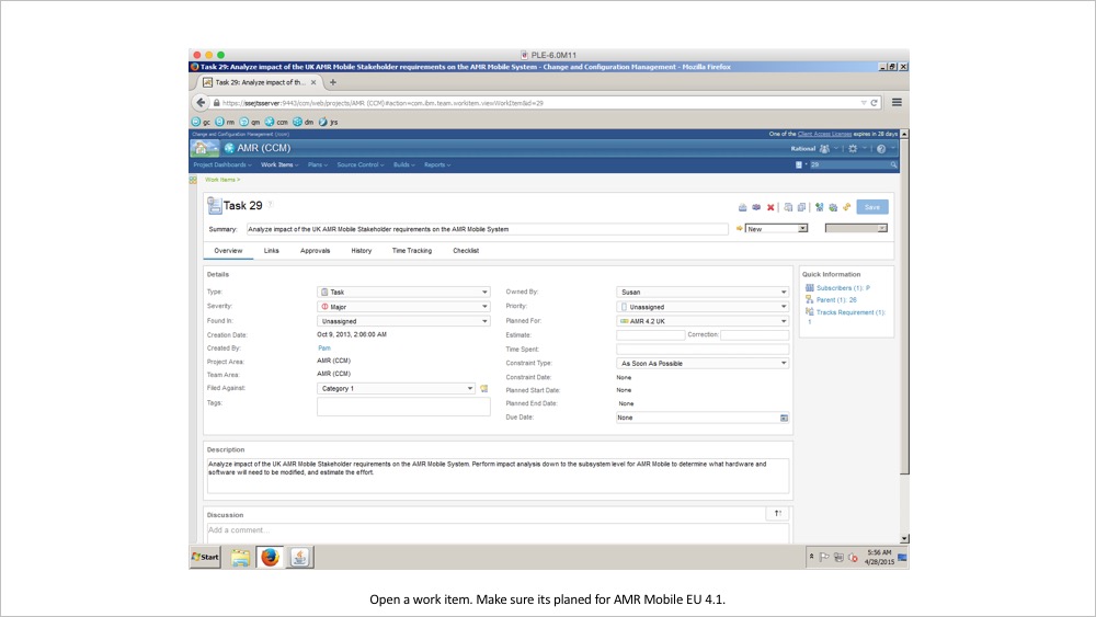
Requirements Change Set – a container for the proposed changes to the requirement(s) in the RM repository
This act in the scenario expands the lifecycle resources to explore the relations to project planning and realization and validation of the changed requirement. These resources include
Release plan – the plan the change request is planned for
Design and Test tasks – the plan items for the team to work on to realize and test the changes
Model elements – impacted requirements captured as models
ChangeSet – the changes to model and code
Build – the first build containing the delivered changes
The test case, Test execution, and Test result – the validation that the delivered changes are fulfilling the changed requirements
The system project is approaching its delivery. The focus of the remaining iteration/increment is to stabilize the release. Process changes where deliveries require approvals. But the main focus is on the system versification
What we learn
In this act, we are deepening our understanding about
How to support the System Verification phase on the System Delivery platform
Collaboration across development and verification teams
Use of measures, dashboards, and reports during stabilization
System Delivery Measures
Completion = how done the project or phase is
Rate = the rate at which work is being done
Quality = the quality and stability of the deliverable
Schedule = the accuracy of the scheduling and estimating process
Complexity = how hard the work is
Systems Engineering Metrics
Requirements analyzed – # of requirements that have been reviewed and allocated to a use case
Use cases analyzed – # of use cases analyzed (incl. scenario elaboration and executable state machine run)
Use cases allocated – # of analyzed use cases allocated into the selected systems architecture (includes
construction of logical ICDs and messaging between architectural subsystems)
Use case complexity – # of transitions + # of actions on use case state machine
Requirements productivity – # of requirements allocated to use cases and to the selected architecture per person-month of effort
Requirements volatility – # of requirements changed
Use Case Defect density – # of identified defects per use case
Schedule variance – % difference between actual effort and estimated effort
Task variance – average % difference between actual effort and estimated effort per task
Software Engineering Metrics
Defect Density – # defects per 1000 lines of delivered source code OR # defects per class
Unit Test Density – # unit tests per 1000 lines of delivered source code OR # defects per class
Use Case Velocity – the rate at which use cases are being achieved (# use cases realized and validation tested / unit time)
Work Item Velocity – the rate at which work items are being completed (# work items completed / unit time)
Test Coverage – # of source lines code tested / total number of source lines of code
Requirements velocity – # of requirements demonstrably represented in design, implementation, and test per unit time
Integration rejection rate – average # of submissions to continuous integration rejected due to breaking the build
Architectural volatility – # of changes made to the software architecture
Validation density – # of tested requirements / # of requirements
Validation test failure rate – # of validation tests that fail / total number of validation tests
Schedule variance – % difference between actual effort and estimated effort
Task variance – average % difference between actual effort and estimated effort per task
Jazz.net Read more about the IBM Engineering Lifecycle Management solutions on Jazz.net.
Systems Lifecycle Management and Systems Delivery with CLM
In 2010 I led to the design of Systems Lifecycle Management and System Delivery scenario with Collaborative Lifecycle Management (CLM).
What is Systems Lifecycle Management and Systems Delivery with CLM
This is one of the scenarios in a family of CLM scenarios exploring the Lifecycle Management practices and how these practices are supported by the Rational tools built on Jazz, or integrated with Jazz.
As the foundational capabilities of Lifecycle Management (process integration between disciplines, traceability of artifact relationships, and project transparency and reporting) are common needs by any delivery project we use a shared approach to the CLM@scale scenario. The CLM@scale scenario outlines the project lifecycle, the roles in the project, and the common practices of a project. For the System Delivery scenario, we configure the System Engineering practices and System Delivery platform by extending the shared CLM@scale scenario. We explore the team workflows of a multi-disciplined project to deepen our understanding of how our systems customers can succeed with System Engineering practices using our Jazz products. We work from the ‘outside-in’ and ground the scenario in the challenges our customers face in delivering systems, or systems of systems, that integrate software, hardware, and electronics.
The objectives of the System Delivery scenario are to Capture System Lifecycle Management and System Engineering workflows across a set of core products.
The shared objectives of the CLM@scale scenarios are focusing on
Getting started. The consumability and administration of our integrated Jazz solution.
Adopting practices. Adding agile delivery practices to team process
Task management. Everyone on the team gets assigned tasks
Planning and transparency. How status rolls up across projects
Automation. Explore how events can be used to create interesting life cycle automation
Measures. What reports and metrics are needed by the team to manage their project.
The System Delivery scenario extends the objectives by focusing on
System Lifecycle Management. Solution completeness for a project of multi-disciplined teams
System Engineering. How the team is performing system requirement engineering and architectural management with Jazz integrated tools.
OSLC adoption. Linking of OSLC resources across a System Lifecycle Management Solution using OSLC.
Traditional planning. How a traditional system delivery project is managed and integrated with an agile software team.
Product planning and delivery. How teams defined and deliver product part structures and variants.
System Delivery Measures. What measures are needed and how these are delivered to the teams through reports and dashboards
The Lifecycle
There are many representations of a project lifecycle. For example, a traditional sequential lifecycle, or an iterative lifecycle flow of incremental phases. System delivery teams tend to use the well-established ‘V-Model’ lifecycle models. Other system delivery teams adopt a spiral flow of incremental refinement. For this System Delivery scenario, we have taken a somewhat generalized approach to a project lifecycle by Flattening the V. This enables us to share a common scenario lifecycle flow across the CLM@scale and System Delivery scenarios. This generalized approach can support key lifecycle management aspects of both the commonly used V-model, and well as the iterative spiral model.
Looking at the V-Model we identify a set of key lifecycle phases; the system engineering phase that establishes the system requirements and architecture, the multi-disciplined engineering and validation teams that deliver the system through a sequence of milestones, the validation, acceptance, and release of the system delivery, and a continuous project management activity that leads the project to completion.
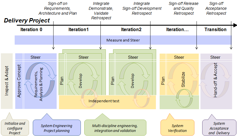
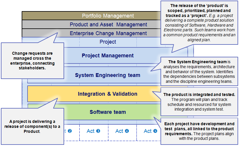
The lifecycle figure is using colors to identify the main focus and ownership of the lifecycle activities.
Gray is used to indicating deployment and configuration activities performed by project administrators and leads, for example, the Inspect and Adapt phase.
Blue is used to indicate activities performed by a cross-project team, for example, requirements analysis performed by the System Engineering team, or the project leadership team planning the project.
Green is used to indicate activities performed by a development team. Such activities may be from multiple disciplines, like iteration planning, development, and component testing.
Orange is used to indicate independent system tests and validation. Such activities are continuous through the lifecycle.
Purple is used to indicate asset management activities. This lifecycle mainly focused on the system hand-off phase.
The generalized lifecycle, shared by the CALM scenarios, recognizes these phases and lay’s them down along a sequential time axis as individual iterations. Taking this approach we can see commonalities in lifecycle management capabilities and needs between applications development and system delivery. We can also explore common workflows that apply to any lifecycle approach. Where exceptions are found we explore them as extensions to the CLM@scale scenario.
The lifecycle, captured in the figure below, generalizes on the lifecycle phases of an end-to-end system release. The phases focus on the system engineering, planning, development, and delivery phases.
The lifecycle starts with the project team preparing for the project (c.f. Inspect and Adapt in the figure). In this part, the project leads and administrators are preparing the system delivery platform, configuring the team practices and processes, and creating the required project areas across the System Delivery platform repositories.
Once launched, the project moves into a System Engineering phase (c.f. Iteration 0 in the figure). The concept defining the release objectives is approved and the system engineering team is analyzing stakeholder requirements, and defining the system requirements, system use-cases, and system architecture. During this phase, the project plans and dependencies between sub-systems and teams are established and approved. For projects delivering systems of systems, it’s vital to establish and track such dependencies as the system delivery may cover multiple disciplines like software, hardware, and electronics. Parts may also be delivered by 3rd parties or sub-contractors. In this scenario, we are focusing the story on the interactions between the project plan and the dependencies to a software subsystem.
The lifecycle proceeds with a sequence of iterations, or spirals, where the development teams are planning, developing, and integrating subsequent milestone releases of the system (c.f. Iteration 1 and 2 in the figure). The milestone releases are integrated and validated by an independent system verification team. As the project is prepared for its final release milestone the teams focus on release stabilization and system test (c.f. final Iteration in the figure below).
At the end of the lifecycle, the system is transitioned to production or deployment. The team finalizes the release by acceptance testing and signing off on the release quality.
As indicated in the figure below, aspects of teem steering are covered in each iteration. There is also project-level steering that measures and monitors the health of the project and the adoption rate of new development practices.
The System Delivery Organization
The system delivery scenario is using a common project organization and common project roles/persona from the CLM@scale scenario. The project is organized in teams of teams.
The system scenario extends the CLM scenario with a set of general teams and roles important to system delivery teams
System Engineering team(s) that is responsible for capturing, analyzing, and prioritizing the system requirements.
System Validation team(s) that is responsible for validating the integrated system against system requirements.
System disciplines, like software/mechanics/electronics, that is responsible for developing and delivering their sub-systems for system integration of the product.
The teams work from a common set of stakeholder requirements, system requirements, and an aligned project plan. The project will plan and track the schedule and resources for system integration and independent system test.
The scenario is using a core set of tools from the System Delivery platform that is built on Jazz or integrated with Jazz. These tools are
Rational DOORS Next Generation
Rational Rhapsody
Rational Team Concert
Rational Quality Manager
The System Delivery scenario is building out a richer end-to-end story from a core set of Open Services for Lifecycle Collaboration (OSLC) scenarios. These core scenarios capture the essence of the resources, steps, and CLMlinks.
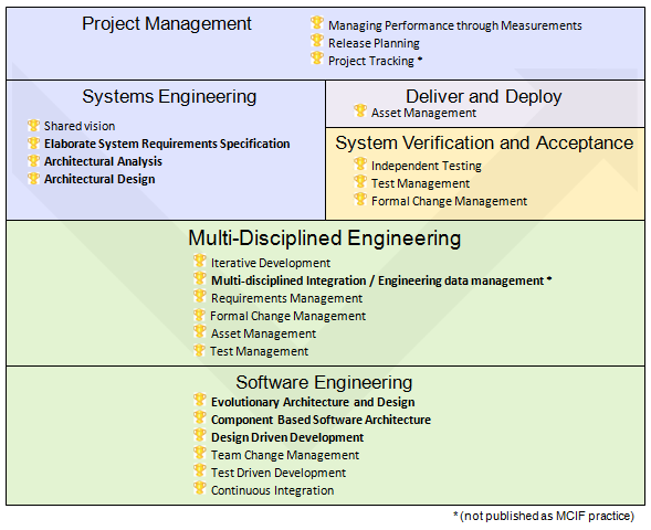
The System Delivery with CALM scenario is based on the practices and tool guidance provided with MCIF. These practices apply specifically to System Engineering phases and to agility@scale practices. The practices apply to specific lifecycle phases as indicated below.
Some of the practices and workflows are common across the CLM@scale scenarios, others (indicated with bold text below) are specific for the System Delivery with CLM scenario.
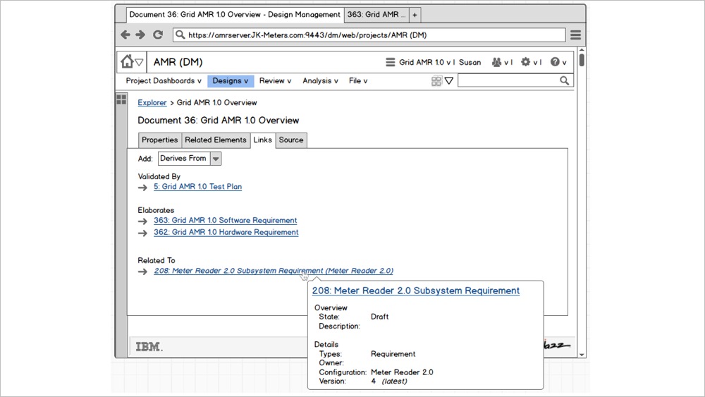
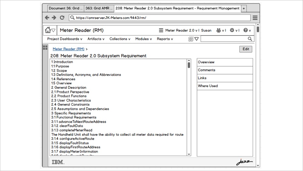
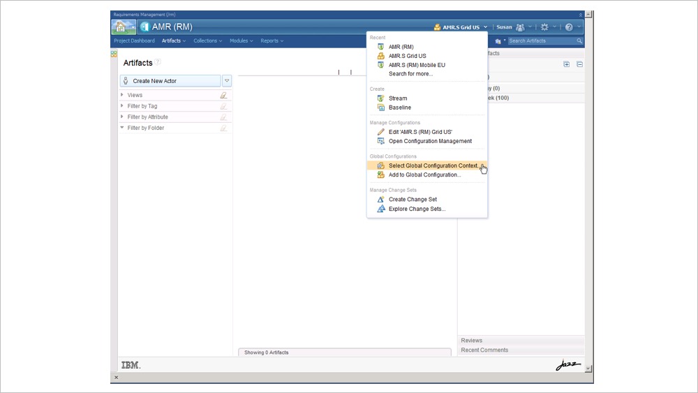
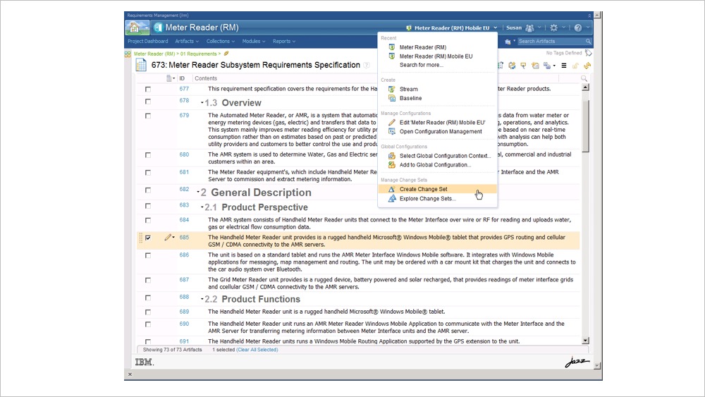
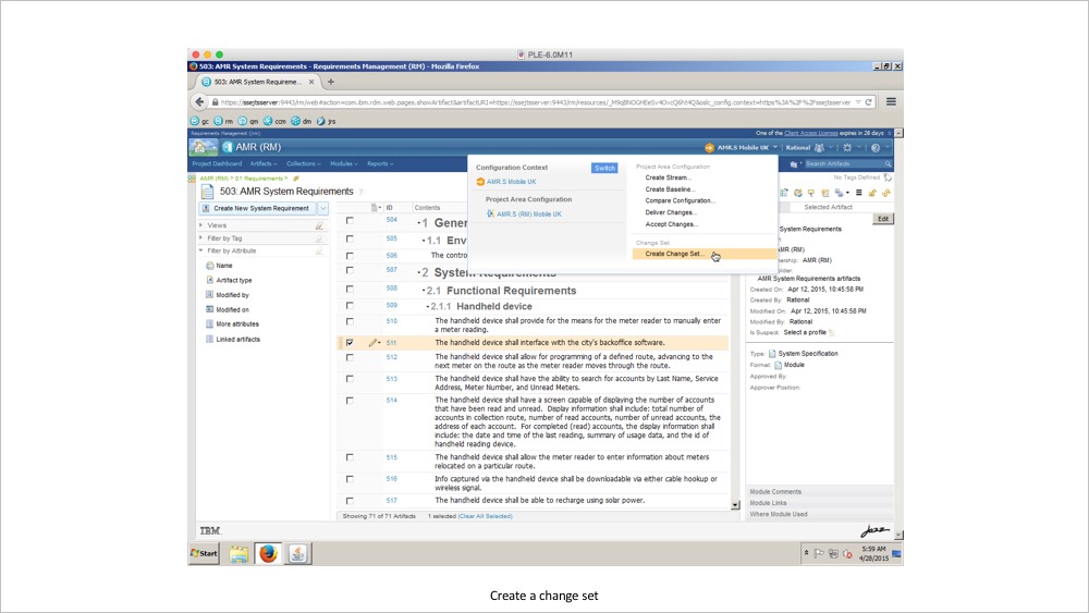
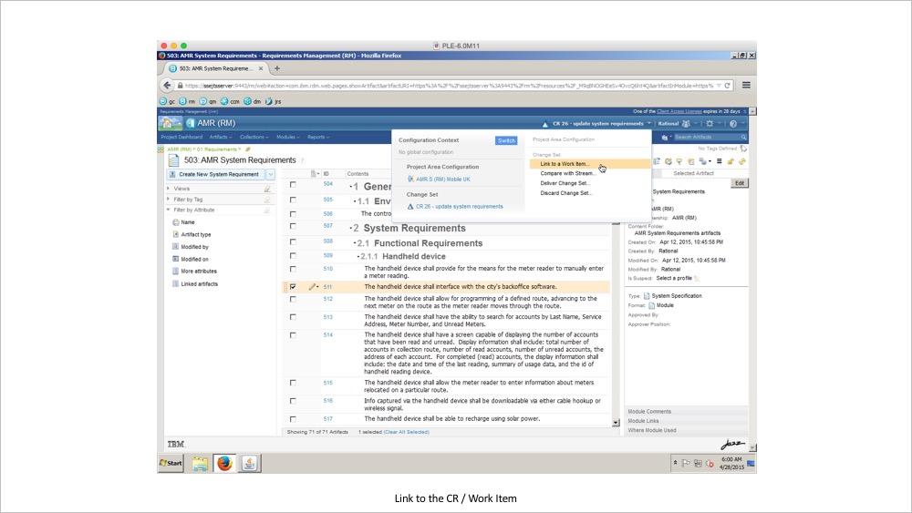
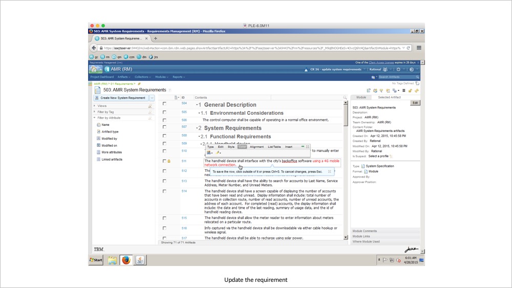
The product line engineering capability adds a Configuration Management menu to the practitioner tools in the IBM IoT Continuous Engineering solution. The menu provides commands to select a configuration context and perform actions on the current configuration context. is a baseline or stream that contains a set of versioned artifacts. A global configuration represents a physical or logical piece of a product offering. It gathers configurations for itself and other contributing applications in IoT Continuous Engineering solutions.
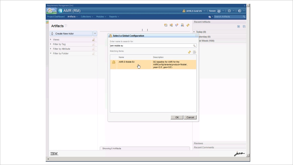
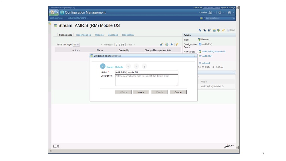
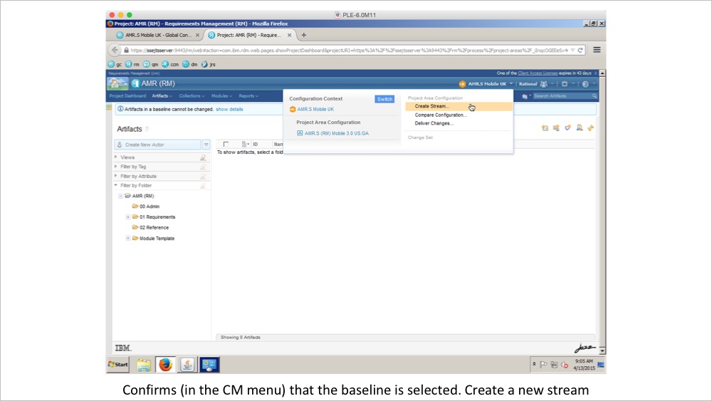
The Configuration Management menu allows users to choose a Project Area configuration of the project area currently opened in the application. The menu also allows users to choose a Global Configuration context. Once a configuration has been chosen, the user may use the Configuration Management menu to create new streams or baselines. Users may also deliver changes from or into the currently selected baseline.
PLE Hills
The hill for PLE states that “Hill 1: Teams enjoy configuration management in and across their ALM tools” and that “With minimal impact to current usage, team members can select a configuration related to their plan and be confident that they are using the right artifacts and links.”
User research identifies the need to scope the capabilities on the Configuration Management menu to the right level of user maturity
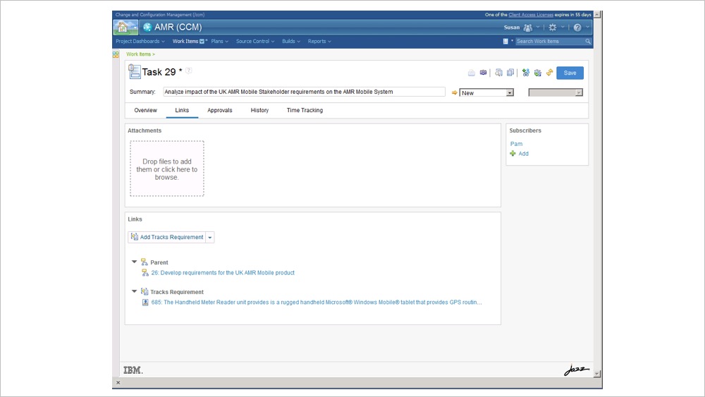
System Engineers and Testers may be assigned work in a configuration. Such a user just wants to browse from the work item into the configuration selected for the work. The user experience for switching into a configuration should now require any action by the user.
Users with no permissions for Configuration Management should not see such actions on the Configuration Management menu
System Engineers with Configuration Management permissions should be presented with menu commands to choose a configuration context.
System Engineers with Configuration Management permissions should be presented links to browse into the definition of a global configuration in the Configuration Management Application
User Experience Low Fidelity Design – Configuration Management menu
Early playback of Configuration Management menu
User Experience High Fidelity Prototypes
Running code prototypes of Configuration Management Application
User Experience – IBM IoT Continuous Engineering 6.0 GA
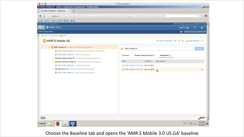
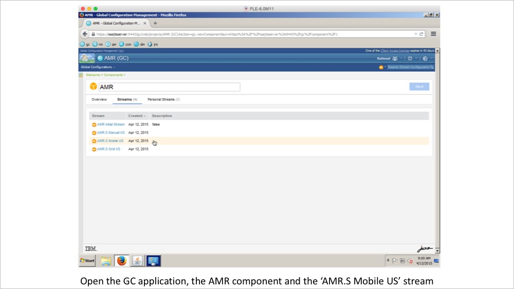
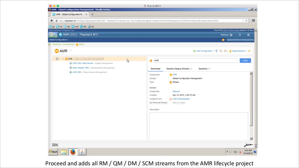
Released version of Configuration Management Application
Global Configuration Management (GCM) is an application that assembles configurations for itself and other contributing applications so teams can gain an overall view of the physical and logical parts of their product offering.
A configuration is a baseline or stream that contains a set of versioned artifacts. A global configuration represents a physical or logical piece of a product offering. It gathers configurations for itself and other contributing applications in IoT Continuous Engineering solutions.
Global Configuration Management integrates with the following CLM applications.
The Requirements Management application (RM) delivers requirements definition and requirements management capabilities.
The Quality Management (QM) application delivers testing and test management capabilities.
The Design Management (DM) application delivers design management capabilities.
The software configuration management part of the Rational Team Concert™ application delivers work item capabilities.
In 2014 I was leading the design concepts for Product Line Engineering in the IoT Continuous Engineering solution.
What is Product Line Engineering
The industry is making amazing IoT innovations in the products, systems, and applications that impact most of our daily lives: from the smallest transistors in the latest microprocessor making the simplest THINGS smarter to the most advanced products like cars, airplanes, transportation systems, city infrastructures and globe-spanning electronic networks we now take for granted. Increasingly powerful yet inexpensive hardware, embedded and cloud-based software, and ubiquitous network connectivity are enabling new levels of intelligence, interconnections, and instrumentation.
The price we pay for this progress is increasing complexity in the designs, development processes, and supply chains needed to create these smarter products and systems. In many industries, development teams are finding their old development processes and tools to be insufficient to meet the challenges. For example, Engineering teams in auto companies have traditionally focused on mechanical engineering; now the majority of the requirements they must address are expressed in software running on the many processors networked together in a modern car.
Smartphone device manufacturers employ an army of programmers to manage the torrent of monthly changes in the Android operating system and evolve their proprietary value-adds. IT application development managers deal with extensive supply chains as they seek to optimize cost, quality, and time to market.
The IBM continuous engineering solution is a set of engineering and development tools that help systems engineers, application developers, and embedded developers work together to create product lines of smart and connected products. A product line strategy helps to address the timeless need to work faster, cheaper and better. For example:
Increase revenue by reaching more market segments/niches. Product variants provide targeted sets of capabilities, price points, and compliance with specific regulatory regimes.
Improve time to market and lower development costs. Products are defined as sets of reusable components in a product line.
Improve quality and lower field service costs. (A) Reusing validated and verified components already in the field results in lower defect densities and field service costs. (B) Engineering tools that can automate the reconstruction of complex product configurations used by clients will reduce field service costs through increased productivity of the engineers, for example, when preparing their environment to find and fix a defect.
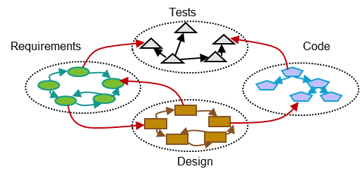
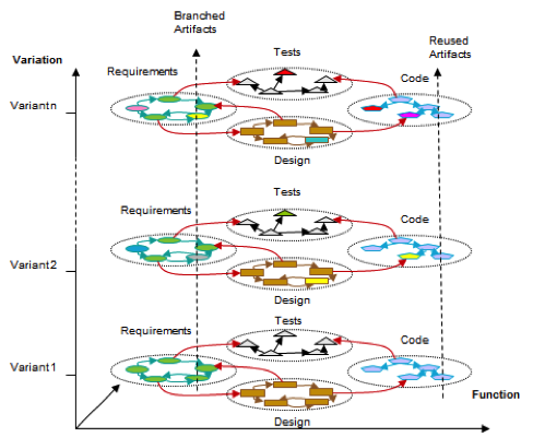
A Product Line is a group of closely related products that are variants of each other. A product is formed from a specific configuration of component parts, often produced from a common base, or architecture, of components. Each component used in a product has associated requirements specifications, designs, software, test plans, and more. These artifacts are linked Requirements are linked to the design artifacts at the system and subsystem level that model the requirements. The design is linked to the implementing code. Tests are linked to the requirements and code they validate. The links declare dependencies and enable traceability and impact analysis..
However, the requirements specifications of each product in a product line are slightly varying. For example, a Compact car has different product requirements as compared to a Premium car. As the requirements specifications are different all downstream artifacts like designs, software, test plans are also impacted.
“Product lines are a development paradigm allowing companies to realize order-of-magnitude improvements in time to market, cost, productivity, quality, and other business drivers. Software product line engineering can also enable rapid market entry and flexible response, and provide a capability for mass customization” – Software Product Line handbook by SEI
A common approach to manage the variability is to use a ‘Clone and Own’ practice. When stating developing a new product variant a copy is made of all requirements specifications, designs, software, test plans, and other associated artifacts. Requirements specifications for the new product variant are modified or added in the copy. Requirements specifications that do not apply to the new variant are removed. All downstream artifacts and traced and updated similarly. While this approach is simple and pragmatic it is ineffective. It is challenging to share components across products and leverage improvements made in one product variant with other variants. Defects have to be coordinated and fixed in every variant individually by each product team. The use of development resources is also ineffective. A system engineer, a system developer, or a tester can not easily switch tasks between project variants. Recreating a development environment with a complete and accurate set of requirements, designs, code, and tests is highly manual and can easily take several hours. Making sure that the environment is correct and consistent with the latest state of all versions is challenging and tedious.
A more effective way of working would be to offload the challenge of variants and configurations to the development tools. Imagine a tool that would manage all requirements, designs, code files, and tests and a structure representing each reusable component in a product, including the system, subsystem, SW, and HW levels. Then, imagine that each of the components has been branched into variants. The tool would manage the changes made to artifacts in each component variant. And then finally, imagine a way to select what variant of each component that would be used by each product variant in a product line. That would be so cool! And as a practitioner, I would be able to just ‘ask the tool’ to present me with the right artifacts for each component by choosing the product variant I wanted to work with. And, then, when ‘asking the tool’ to switch to another product variant the tool would transparently just present the right artifacts of the new variant. Just like that, switch configuration in seconds. That simplicity of operation and assurance of correct artifact version is the value proposition to enterprise-sized systems delivery organizations that are challenged by the market demands of delivering product variants and inefficiency of managing the development of the product lines.
Artifacts, like the products they describe, have versions. A version of an artifact is identified by a specific set of characteristics and can exist at the same time as other versions of the artifact in other configurations. Artifacts are contained by components to make them easily tracked and reused. Product line engineering adds configuration management to enable System Engineering teams to effectively work on changes for a given product variant.
PLE design strategy
Our objectives are to design PLE by adding capabilities to our existing Application Lifecycle Management tools and articulating best practices, rather than creating a new PLE tool
PLE aspects concern the entire development process. This strategy focuses on the supporting infrastructure for artifact management and reuses needed to support PLE practices.
Specifying a multi-domain product structure – What is exactly the product?
Consistently manage asset versions and product configurations across all lifecycle disciplines – Create cross-product baselines
Effectively handling change propagation to the multitude of variants – Where does this change need to go
Effectively creating new product configuration based on functional parameters – What features define my new product variant
This strategy enables
Product development teams to
Achieve high levels of reuse and parallel development
Define and work in the context of the products and components they are developing
Engineer product lines
Work across engineering domains
Employ version and configuration management across these domains
Federated data that is created and managed by multiple tools from multiple vendors
Use open standards and specifications
Enterprise-scale with worldwide teams
Hills
My research and analysis led our design to two key System Engineering personas and two PLE hills
Hill 1. Teams enjoy configuration management in and across their ALM tools
With minimal impact on current usage, team members can select a configuration related to their plan and be confident that they are using the right artifacts and links.
Configuration Leads can define configurations of a product under development consisting of requirements, tests, designs, and implementation.
Teams work in a scalable environment with 1000s of configurations consisting of artifacts managed in multiple tools and links within and across those tools.
Subhill 1.1 Fine-grained components in RDNG and RQM
Subhill 1.2 Impact analysis using validity assertions
Subhill 1.3 Report from the lifecycle index with versioned data from GCM, RQM, RDM, RTC, including using data currently missing and data related to plans and project areas
Hill 2 – Technical foundation
Provide and adopt service additions for multi-stream configuration management in Foundation, DNG, RQM, RTC, and DM
Provide and adopt a Global Configurations SDK
Provide and adopt Link service
Enable configuration-aware aware dashboards and product artifact views, including document generation and TRS data feeds in RQM
Enable configuration-aware TRS data feeds in RDNG, RTC, DM and fill the data gaps in RTC, Foundation
Provide and adopt validity service
Use-Cases
Product Line Engineering capabilities should enable development organizations to
Decompose products into (independent) reusable components, like requirements modules, test plans, and design packages or blocks
Develop new products by reusing and modifying components
Develop and release a platform of reusable components that can be combined into new variants of products
Develop and release components of related requirements, tests, designs, and implementation into a reusable global configuration component
Re-factor artifacts across components within the same project area, split and merge components within the same project area.
Work in parallel when developing, releasing, and using variants of reusable components
Compose products under development from both released immutable component baselines and mutable component streams
Overview of the product, its parts, and the component configurations
Select a product configuration context, and then work, either collaboratively or in isolation, on changes in and across multiple components
Deliver or merge changes made in one component configuration to other component configurations
Report on components and their metadata, configurations and their metadata, and the artifacts in a configuration
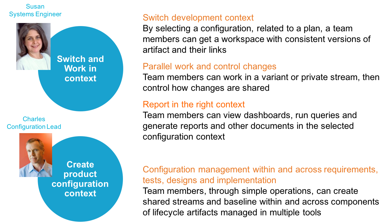
The Product Line Engineering hills call out two major use-cases
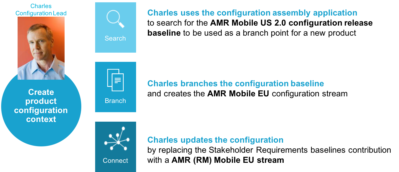
The Configuration Lead creates a new product configuration
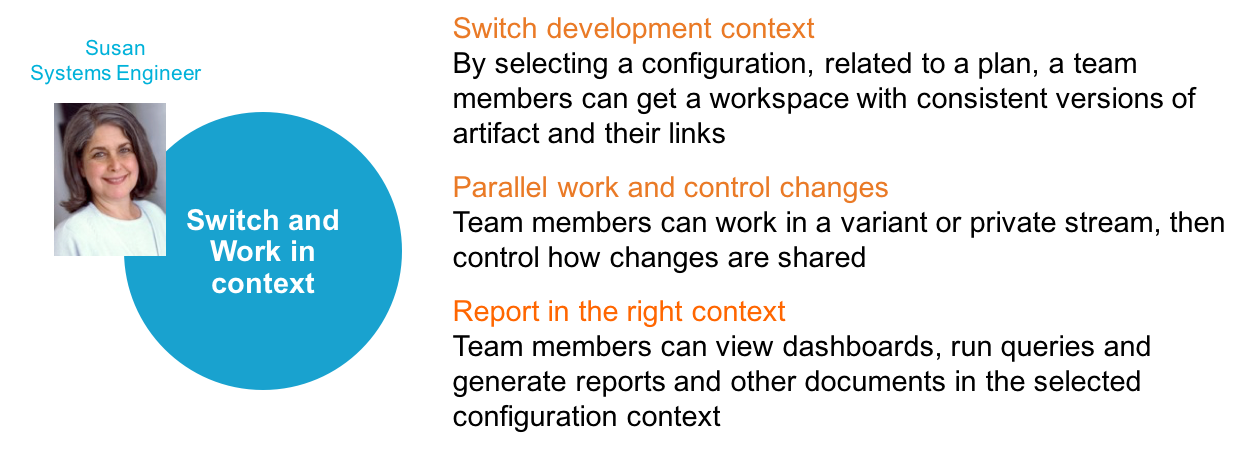
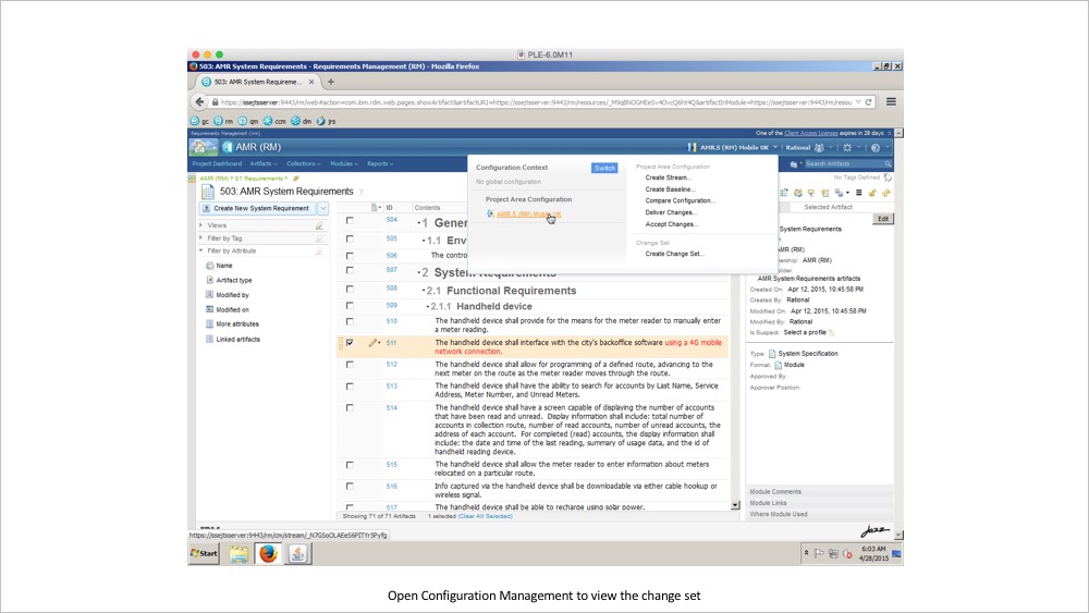
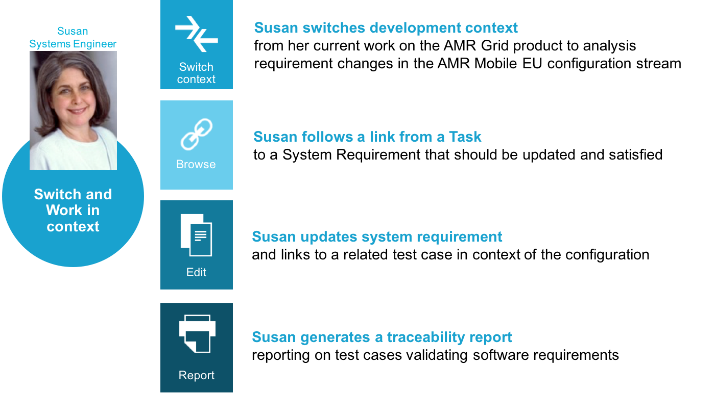
The System Engineer switches into and starts working in the context of the new configuration
Use-Case – Create a new product configuration
Use-Case – Switch and work in a context
“We have 30 products in our product line with 5 variants of each product. We release every product variant 2 times every 18 months with about 30-45 new features in each release. A product contains 300 modules with 500 reusable objects per module. The release roadmap and mapping it to the requirements is a pain point.”
“Our current pain points are; Traceability analysis and baselining Feature change management, and Product change management. We need to view requirement states across all releases.”
“Your PLE 2014 Design Hills and direction resonate well with our needs. We have been waiting for this solution for years”
“Very glad you are being intentional about minimizing impact to existing users and enabling users to adapt better reuse patterns for reuse incrementally — that’s critical. We can’t expect to start from scratch. This has to be accessible to our teams without heroic changes to how they are working now.”
After seeing the playback and our discussions at the Sponsor User call today, here are some quotes from my team: “big leap forward”, “great progress”, “these demos can impress some of our executive people”
Read more about Strategic reuse and product line engineering in an article by Eran Gary, Distinguished Engineer, Rational Continuous Engineering.
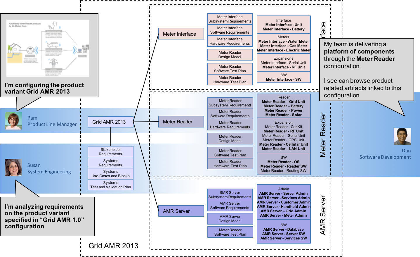
The Automated Meter Reader scenario, used in Product Line Engineering design, uses a fictitious company JK Meters Corp, aspiring leaders of Smarter Flow Products for Utilities.
About JK Meters Corp
The Metering Division at JK Meters Corp has a range of Automated Meter Reader products in its product line. The innovative flow detection solutions combine flow sensors, digital monitors integrated with network communication features that are installed both above and below ground, units for gas and water pipe and pump attached flow control, along with meter reader equipment to commission and extract metering information, increasingly using wireless technologies. The Metering division also develops applications that provide industry partners and consumers with analytics on consumption, diagnostic, and status and solutions for customer billing and service management.
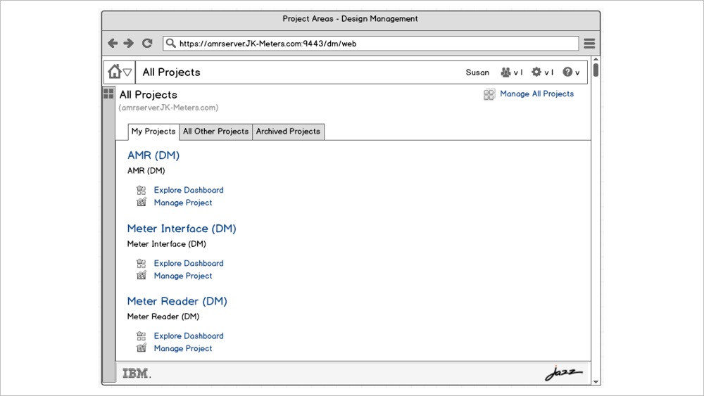
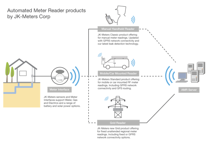
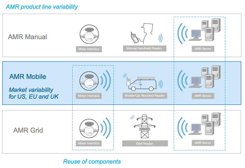
The most successful product is the Automated Meter Reader for Water Flow (see figure below). The product consists of meter interface units mounted on water pipes. The meter interface unit measures flow and delivers data to handheld or car-mounted meter readers. The registered meter readings are uploaded from the handheld devices to the AMR server data management system manually. Uploading of data is performed continuously by the mobile meter readers using a mobile network connection, or manually when returning to the office at the end of the day when using the manual meter reader product.
The Automated Meter Reader products are delivered to utility customers worldwide and the products are developed with variants for each regional market. The variants are configured for regional requirements on power voltage, dimensions on pipe mounting, regional units of flow and volume, language configuration for the handheld meter readers, and regional city maps for GPS routing.
The Metering Division is currently investing in improved features in the product lines and new AMR products. An innovative new AMR Grid product reduces the operational cost of utility services by providing fixed grid meter readers that continuously read a wireless grid of residential or industrial meter interface units and uploads data over a fixed network connection.
About the Organization in the Metering Division
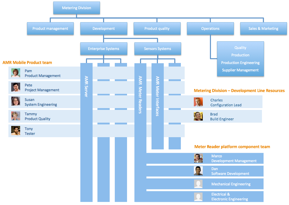
Under the direction of Product Management and Sales, the Metering Division organizes Development, Product quality, Operations with production and maintenance in North America, Europe, India, and China. Development is organized around Enterprise systems for IT, business, and analytics applications and products, and on Sensor systems with integration of sensor technologies and devices. 3rd party suppliers are used for some sub-system development and delivery (not emphasized within the current scenario). The Metering Division teams are distributed and rely on a common product and systems development lifecycle infrastructure for development collaboration and product delivery.
The Metering Division organizes its Development in a matrix of projects and disciplines. The disciplines, managed by discipline managers, are responsible for the definition and continuous improvements of practices and contributor skills. Team members from the discipline are assigned to the project organization and work in the product development team under the leadership of a project manager.
The success factors for the Metering Division Development is to achieve better use of development resources by improving the reuse of parts through product configurations, improvement in product quality, and productivity improvements through collaborative design of hardware and software sub-systems. JK Meters Corp has the initiative to improve the performance of its development and delivery activities for the Metering division. The AMR product development team has deployed IBM Rational’s Systems and Software Engineering solution are currently using change management (CM), requirements management (RM), model-driven systems engineering (MDSE), and quality management (QM) capabilities.
About the AMR Product Line
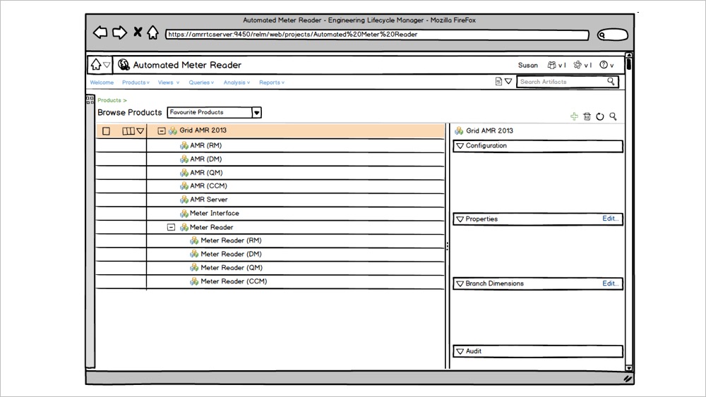
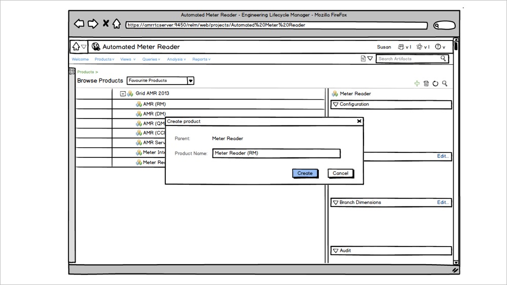
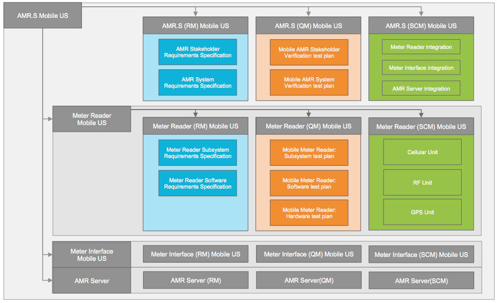
The Automated Meter Reader products are configured from reusable components. These component subsystems are developed and delivered by the Meter Reader, Meter Interface, and AMR Server platform teams. The AMR Manual product is configured from a Wired Meter Interface unit, a Manual Handheld Reader, and a generic AMR Server that is reused across the product line. The AMR Mobile and AMR Grid reuses the Wireless Meter Interface unit but differs in using a Mobile reader vs Grid Reader.
The Automated Meter Reader products have been delivered to utility customers in the US. JK Meters Corp is growing its market share by developing variants for other regional markets. The variants are configured with regional requirements on power voltage, dimensions on pipe mounting, regional units of flow and volume, language configuration for the handheld meter readers, and regional city maps for GPS routing. Meter Interfaces, Mobile Readers, and AMR Servers are adapted and regional variants are created for each market in the US, EU, and the UK.
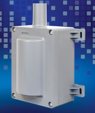
The AMR Meter Interface is an electro-mechanical unit that connects to water pipes, gas pipes, or electrical cords and measures flow consumption and triggers alarms based on events and analytics. The unit is based on a standard microcontroller that connects to a sensor and runs the AMR Meter Interface embedded software and additional drivers for the sensor type. Backup power and communication components are attached to the controller.
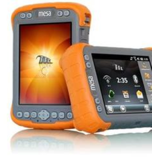
The Handheld AMR Meter Reader is a rugged handheld Microsoft® Windows Mobile® tablet that connects over wire or RF to Meter Interface units for reading and uploading water, gas, or electrical flow consumption data and alarms. The unit provides GPS routing and Cellular GSM (EU) or CDMA (US) connectivity to AMR servers.
The unit is based on a standard tablet and runs the AMR Meter Interface Windows Mobile software. It integrates with Windows Mobile applications for messaging, map management, and routing. The unit may be ordered with a car mount kit that charges the unit and connects to the car audio system over Bluetooth.
Handheld AMR Meter Reader Parts
Windows Mobile tablet
Windows® Embedded Handheld 6.5 operating system
AMR RF expansion unit + AMR RF unit drivers
GPS expansion unit + GPS unit drivers
Cellular GSM and CDMA expansion units + Cellular unit drivers
The AMR Grid Reader is a fixed meter reader that connects over RF to Meter Interface units for uploading water, gas, or electrical and reads flow consumption data and alarms. The unit provides fixed internet or Cellular GSM (EU) or CDMA (US) connectivity to AMR servers. The unit is based on a standard ARM processor board and runs the AMR Grid Meter Reader Linux embedded software. The unit is equipped with an RF antenna, solar panel power, and a backup battery unit. GSM/CDMA or Ethernet cards are attached directly to the board.
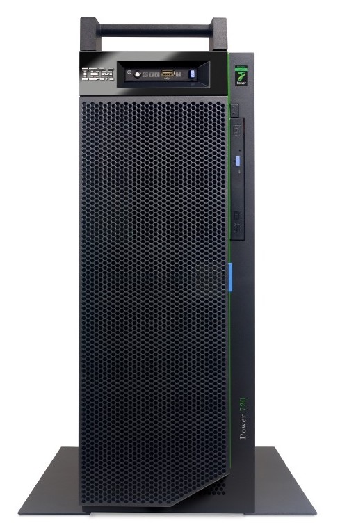
The AMR Server is provided with our IBM partner using the PureData Systems solutions and runs the ARM Server data storage and services applications. JK Meters and IBM offers on-premise, hosted, or cloud configurations.
The AMR Server delivers the AMR data store, the AMR analytics engine, and system administration applications for a customer, infrastructure, operations, and system management. The system also delivers AMR services like billing, reporting, reading, alarms, forecasts and flow analysis, and infrastructure planning.
AMR Server Software Parts
AMR Administration
Server administration
Services administration
Customer administrations
Device administration
GRID administration
Handheld administration
Meter administration
Reusable Platform Components and Variant Product Line Configurations
The Automated Meter Reader products are configured from reusable components. These component subsystems are developed and delivered by the Meter Reader, Meter Interface, and AMR Server platform teams. The platform teams deliver the component subsystems with feature variability for the product line. For example, the Meter Interface team delivers wired and wireless variants of the component for the Manual and Mobile products. The Meter Reader team delivers variant components for Manual, Mobile, and Grid products.
The Product Line Engineering capabilities in the IBM IoT Continuous Engineering solution is providing support to manage variants of components.
What is a Component?
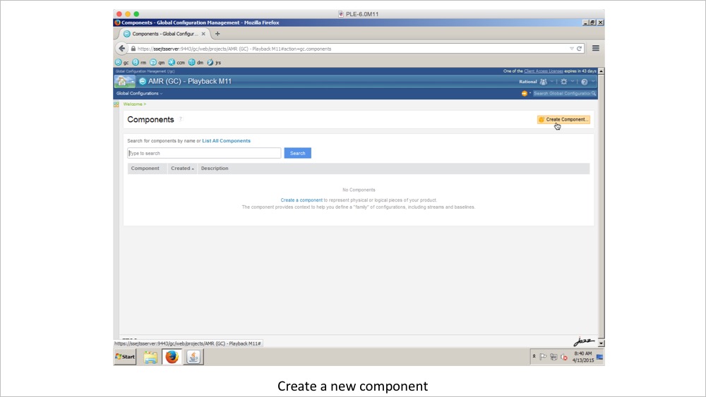
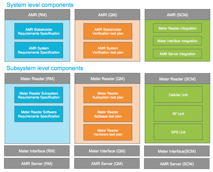
A component is a unit of organization consisting of a reusable set of artifacts such as requirements, tests, designs, and source code. The Automated Meter Reader (AMR) teams are using components to organize the lifecycle artifacts under development. The teams have defined components both at the system/product level and at each subsystem level. Separate components are used to manage requirements, tests, designs, and source code at each level.
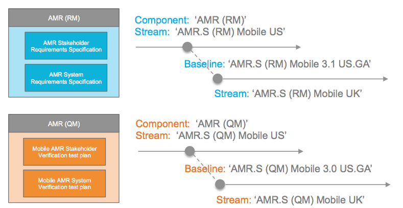
A configuration is a set of specific artifacts versions of a component. A configuration evolves as changes are made to the artifacts in the configuration. At different times it might contain different sets of artifact versions. Such a configuration is also called a stream. A stream can contain changes and is mutable. Snapshots of configurations (streams) at a certain time are called a baseline. Their role is to record a configuration state for either a comparison or simply later reuse. Baselines, can’t be changed, they are immutable.
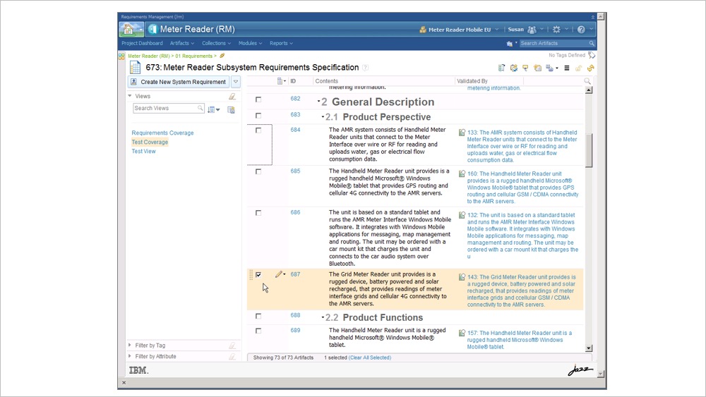
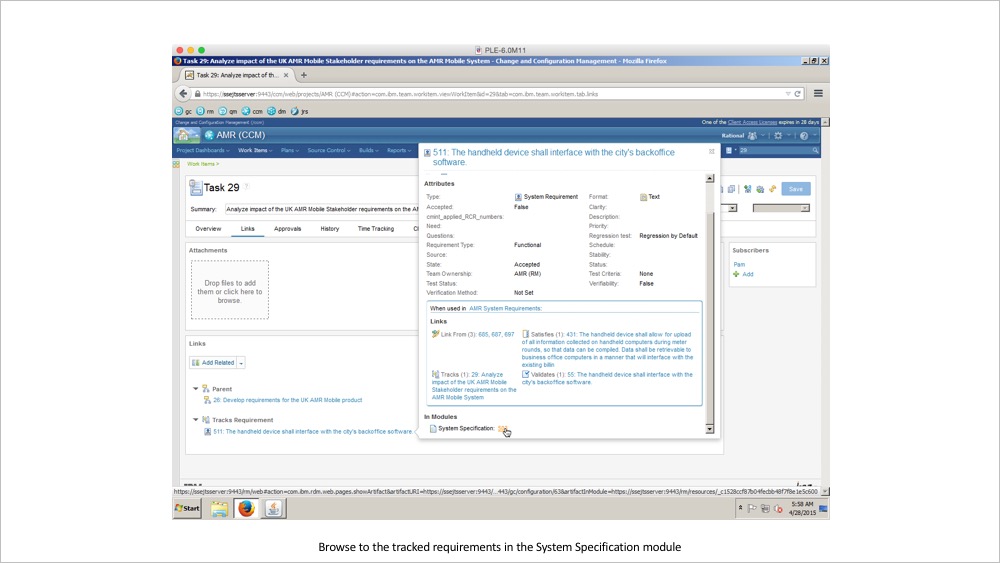
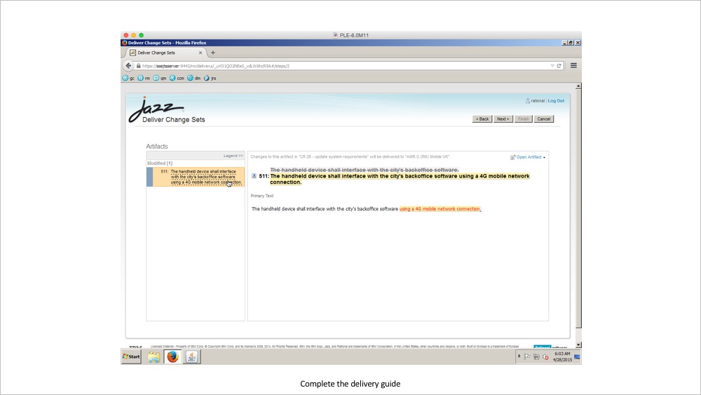
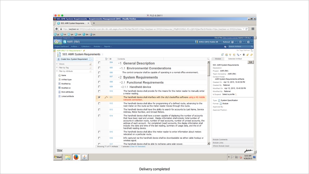
As a configuration is a set of specific artifacts versions of a component, the use of two configurations for AMR system requirements will greatly help in managing the variability of artifacts across the US and UK markets. In two such configurations, common requirements will have the same artifact version but a specific requirement for the UK configuration will have a different version as compared to the US configuration.
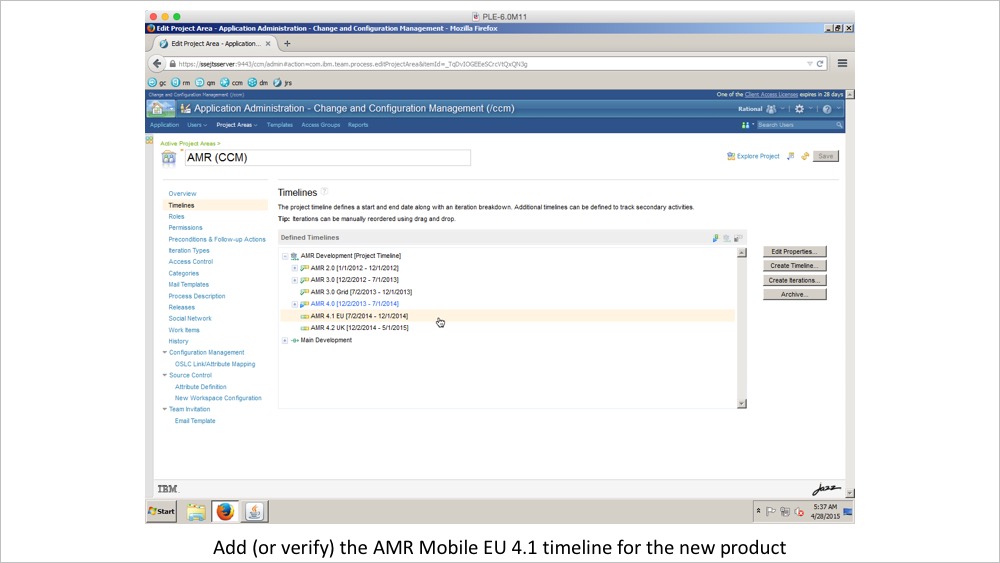
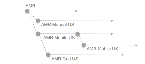
The AMR teams are using several streams to manage variability across the product line. Streams are branched for the Manual, Mobile, and Grid products. Streams are also used to manage variability across regional market US and UK products. The stream diagram below shows a conceptual view of the configuration dependencies.
The AMR teams create baselines consistently across all artifact types for each milestone and release. The baselines are used to branch new streams for changes going into the next product release.
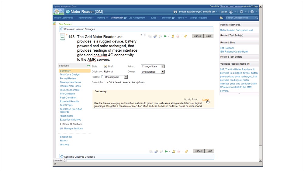
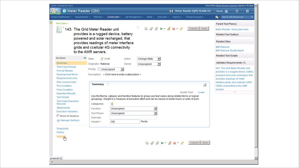
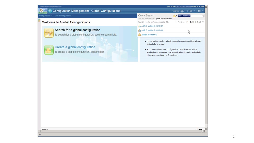
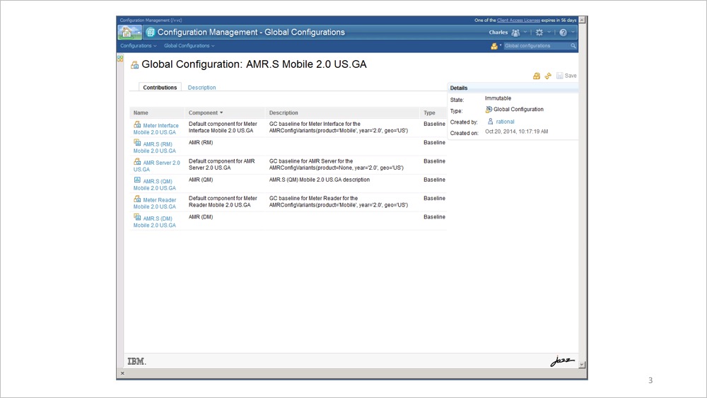
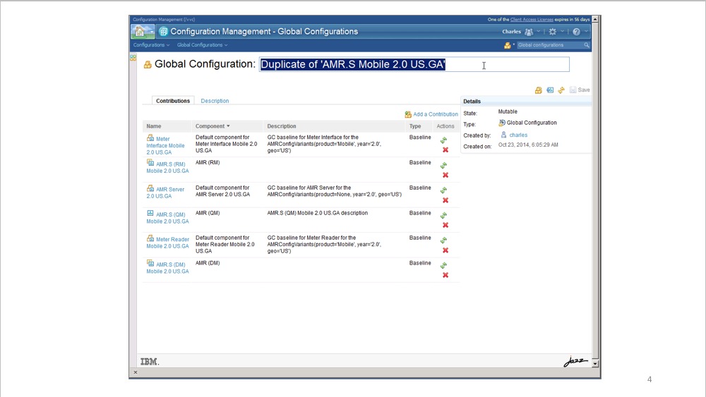
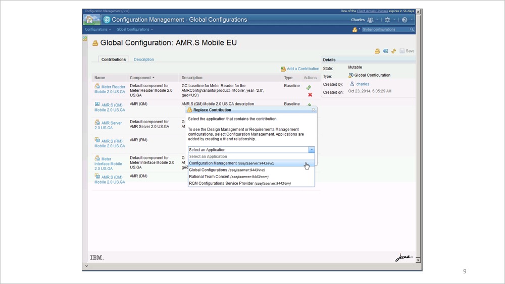
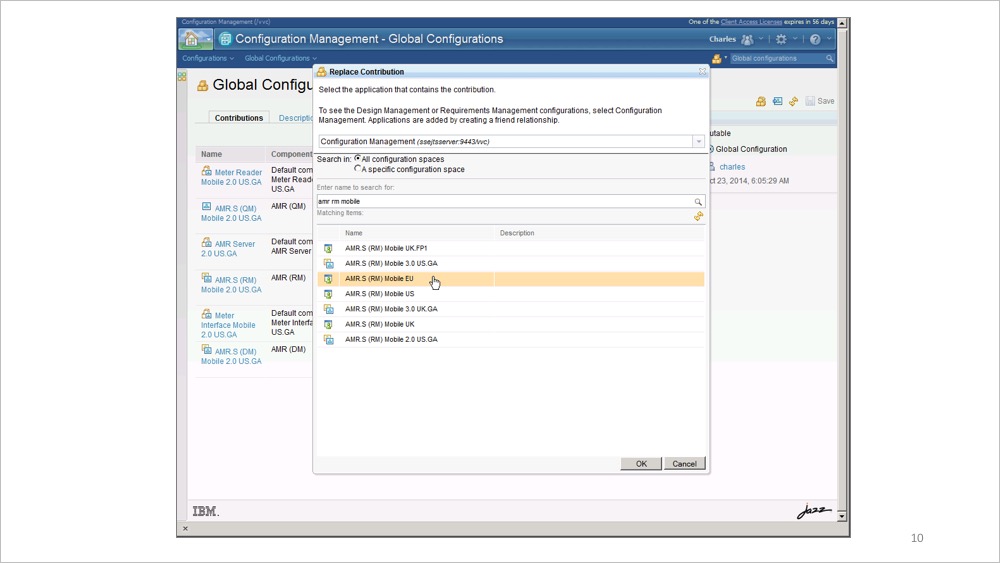
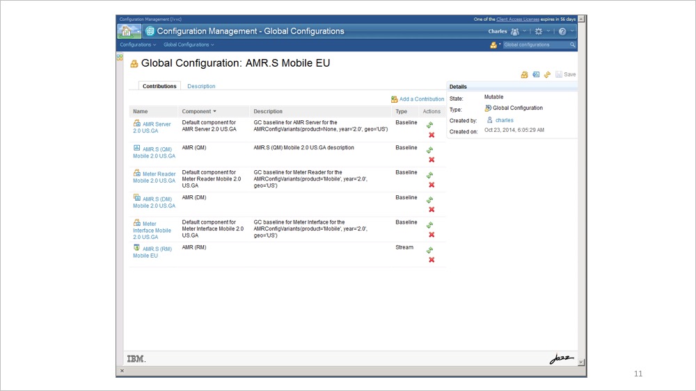
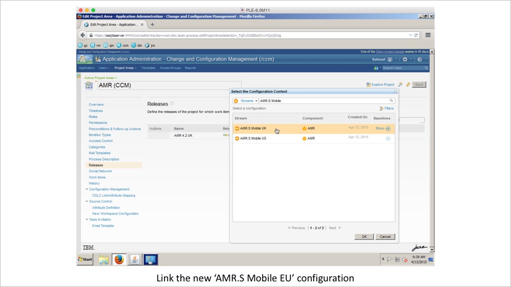
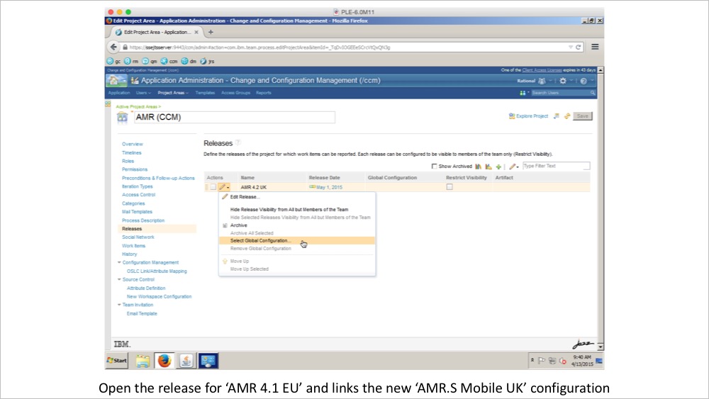
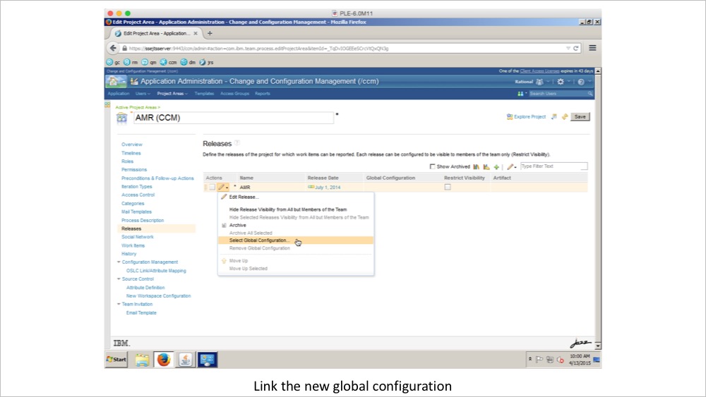
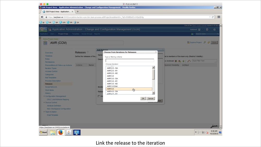
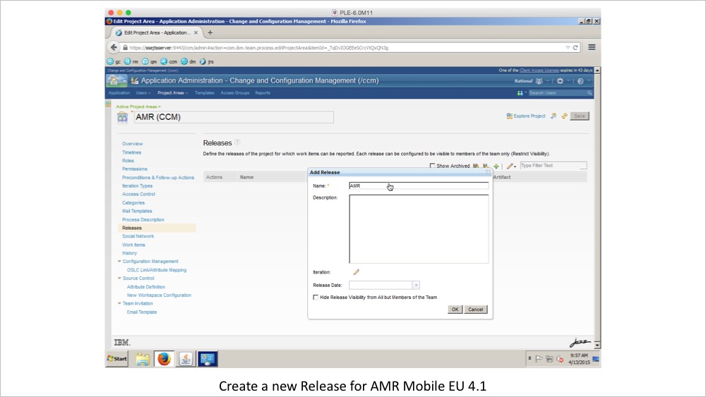
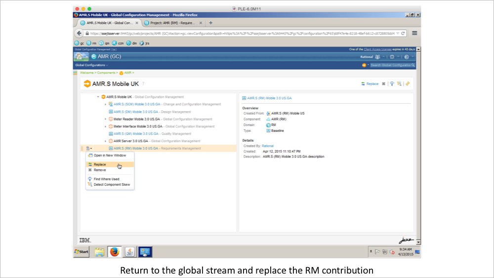
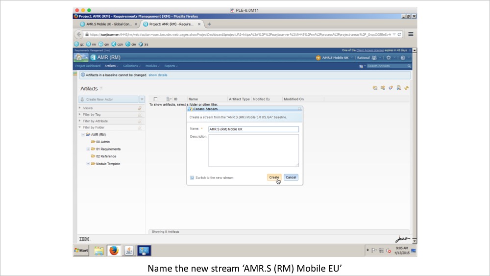
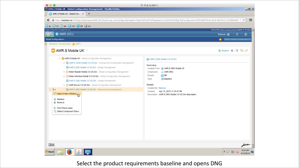
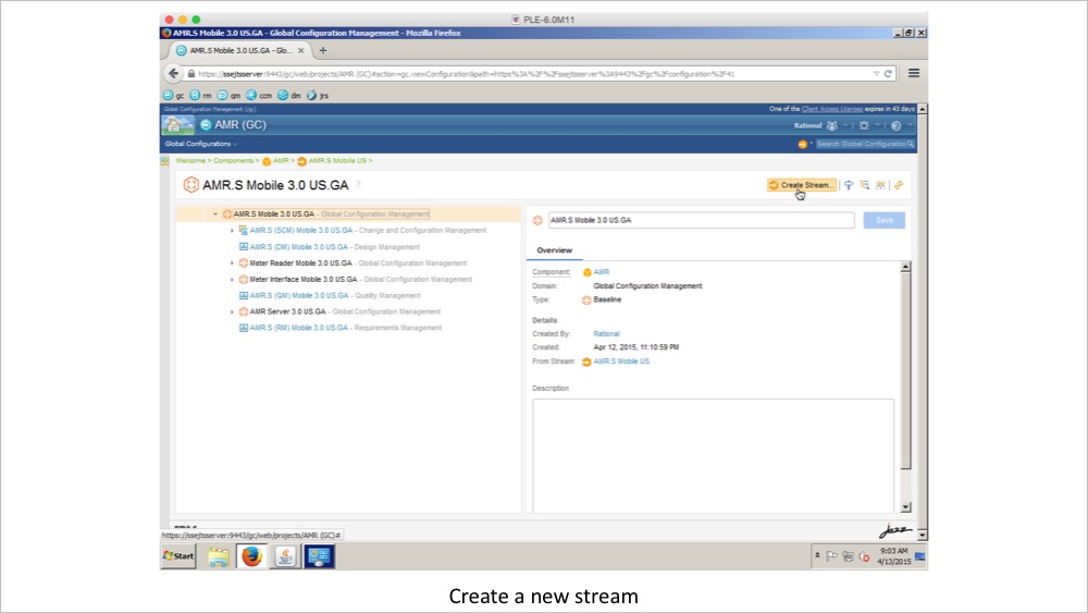
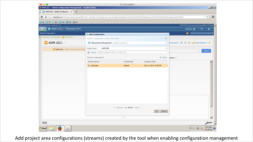
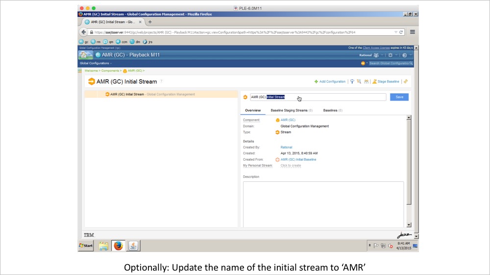
The AMR teams are using global configurations to organize the components for the system level. This enables the system requirements, design models, tests and source code to be managed as a single global configuration. You will use the IBM Rational Configuration Management application to create an AMR Mobile UK global configuration that assembles the requirements and test streams for Mobile UK you created in the previous part. The Automated Meter Reader (AMR) platform teams are using individual global configurations to develop and deliver the Meter Reader, Meter Interface, and AMR Server subsystems.
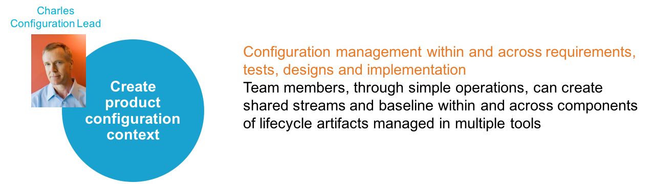
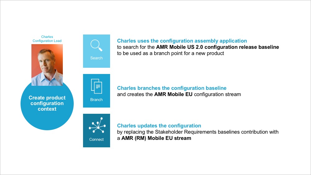
Charles, Configuration Lead. Charles is in the engineering organization. He is supporting the team(s) by administrating and creating stream and baseline configurations. He has a good product line overview and makes decisions on the best options for component versions.
Susan, Systems Engineer. Performs requirements analysis, modeling, and simulation to manage complexity. She collaborates with lead engineers from various hardware and software disciplines to design the system to meet stakeholders’ needs.
Pete, Project manager. Pete is managing the schedule and scope of the Mobile AMR 2013 UK project. He creates and assigns tasks across the team. He makes sure reviews are made and approvals are given. He makes sure the state of artifacts is kept by initiating that baselines are taken. He tracks project measures and makes sure artifacts progress to completion.
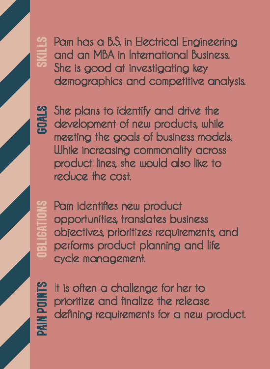
Pam, Product Manager. Pam is in the marketing organization. She works closely with customers to understand market needs and opportunities, and defines and manages products and variants to meet customer needs
Dan, Embedded Software Developer. Creates the software design model and implements the System Engineering model. Designs, implements, and unit test the software model using Model-Driven Development.
Allison, Tools Administrator. Installs, Configures and Maintains tools in production. Maintains project templates and creates tool repositories using templates.
The personas appear in two types of development teams.
The AMR Product teams deliver product variants for multiple markets
The AMR Platform team delivers reusable components for the product teams the Platform team
The AMR Mobile Product team is responsible for delivering the mobile product variants to the US, EU, and UK markets. The team reuses and refines components delivered by the platform component teams. The AMR Meter Reader platform component team is responsible for delivering reusable components for the AMR project line. The teams share resources for stared tasks, e.g Configuration management, Build, and Tool Administration. Separating the responsibilities of Project and Platform teams is significant and captures patterns of organizing teams and practices around effectively developing product lines.
AMR Mobile Product team
The personas appear in two types of development teams.
The AMR Product teams deliver product variants for multiple markets
The AMR Platform team delivers reusable components for the product teams the Platform team
The AMR Mobile Product team is responsible for delivering the mobile product variants to the US, EU, and UK markets. The team reuses and refines components delivered by the platform component teams. The AMR Meter Reader platform component team is responsible for delivering reusable components for the AMR project line. The teams share resources for stared tasks, e.g Configuration management, Build, and Tool Administration.
Separating the responsibilities of Project and Platform teams is significant and captures patterns of organizing teams and practices around effectively developing product lines.
Susan Systems Engineer B.Sc., Mechanical Engineering M.Sc., Systems Engineering
“I see the big picture to manage the complexity of the system”
Susan has been with the current company for about 10 years and has over 20 years of systems engineering experience in the industry. Her current project is building a smarter hybrid car. She has a BSc. in Mechanical Engineering and a graduate degree in Systems Engineering.
As part of her daily job, Susan uses a host of tools that include modeling and simulation, requirements analysis to manage complexity. She collaborates with lead engineers from various hardware and software disciplines to design the system to meet stakeholders’ needs, but also interacts with stakeholders to manage their expectations and to complete the project on time and within budget. She constantly monitors and investigates how all the pieces in the system fit and work together, but currently, it is not always easy to get a big picture view of the entire system or up-to-date information on components in the system.
Responsibilities
Collaborate with domain leads to perform. requirements definition, modeling, top-level functional designs to organize and coordinate other engineering activities. Susan collaborates with product management, project management, test, and design. Lifecycle cost analysis is performed by IPT (Integrated Product Team) lead.
Act as the primary interface between management, customers, suppliers, and specialty engineers in the systems development process.
Susan works closely with marketing to understand customers’ needs and works with tools architects to ensure tools/processes match everyone’s needs.
Support change review board.
Ensure complete requirements traceability from business requirements to systems to subsystems.
Goals
Manage the complexity of the system.
Detailing the requirements of the system.
Defining, characterizing, and documenting. subsystems and the interactions among them.
Organize and coordinate systems development activities and processes.
Pain Points
Get a big picture view of the entire system or up-to-date information on components in the system- large dependency of tools knowing how to extract needed information.
Maintain awareness of changes throughout the systems development process, more importance on the solid process for change management (change records, review proposed changes). This includes both formal (reviews, propose changes) and informal (drafting, fewer reviews of each change, in preparation for peer reviews) change control. There are two main pain points here : (1) changes to requirements coming from different sources (2) communicating the change with the team.
Maintain and communicate to ensure all stakeholders are on the same page about the system requirements, design, and so on. This is part of the formal change control (stakeholder reviews as part of the change.
Identify where different members of the cross-function team are to be involved.
Oversees preparation of reports, such as statistical and data analysis reports, for all engineering processes.
Oversees policies, procedures, protocols, and controls that govern operations.
Balance across products and identify what is common across products and reuse.
Ensure architecture integrity in the system and make all architectural design decisions
Review and approve architectural changes
Goals
Organize and coordinate systems development activities and process
Work with Systems Integration Organization to ensure integration of components from various disciplines into a coherent and effective system.
Pain Points
Have appropriate tools to help with productivity and process guidance – heavily reliant on a requirements management tool (DOORS), users must be effectively trained.
Create a baseline of artifacts stored in all tools used in product development.